


Designing an Ethernet-APL Field Device: Hardware, Firmware and 10BASE-T1L
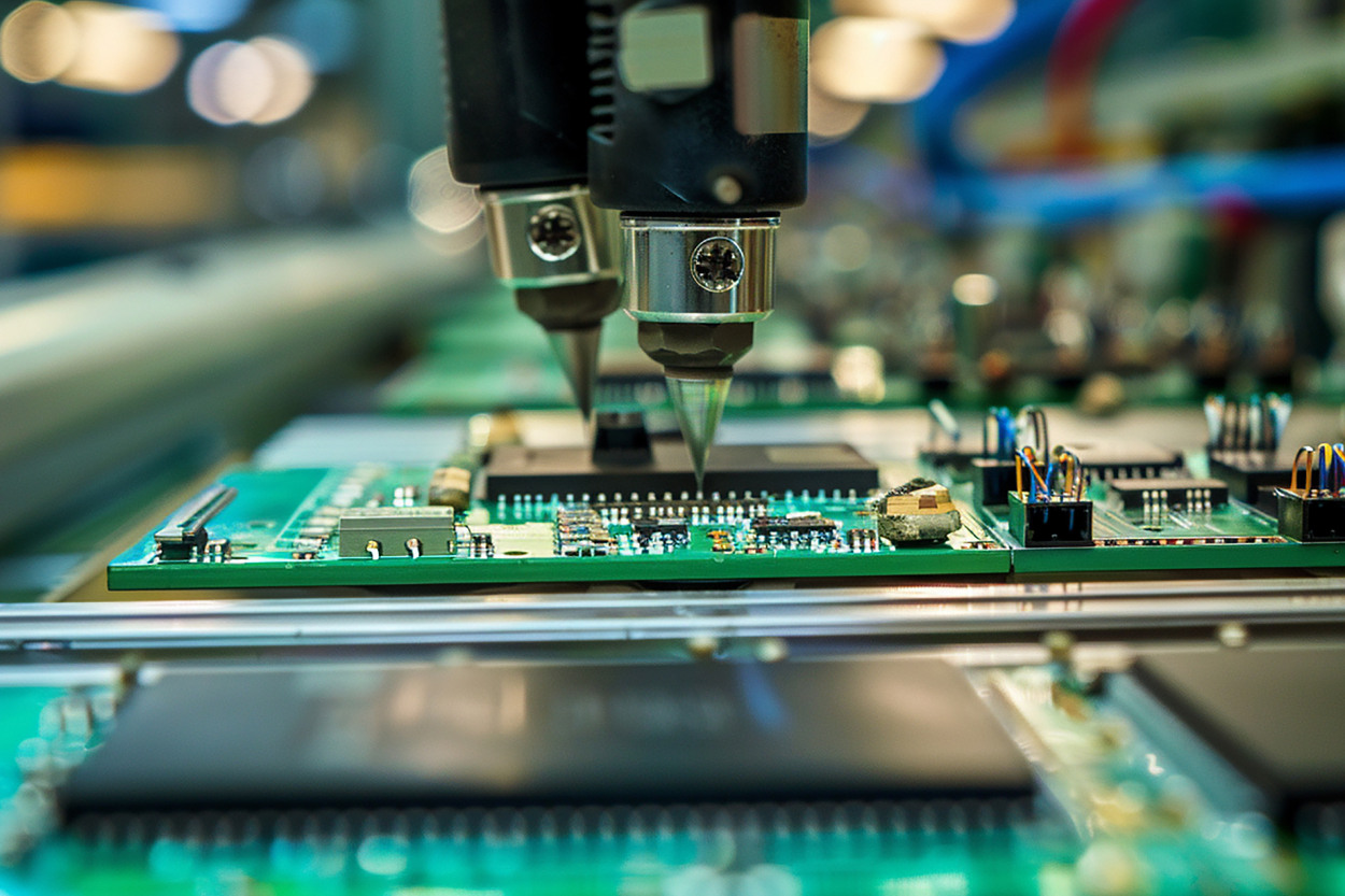
A common development pattern looks like this: the evaluation board links reliably on the bench, a PROFINET controller finds the device, and the team moves on to the schematic review.
Then the first custom board shows less link margin than the evaluation kit on the same cable. The sensor front end picks up noise whenever the SPI bus moves a full-size frame. On a powered spur, the device browns out during a firmware update, because flash erase, sensor excitation and the MCU at full clock land in the same few hundred milliseconds. The PROFINET stack and the OPC UA server compete for the same RAM, and nobody has decided what the device should report when the cable degrades but the link stays up.
None of this is a 10BASE-T1L problem. The PHY does what its datasheet says. The trouble sits between the PHY and everything else: the power budget, the coupling network, the board layout, the firmware structure, and the evidence a test lab will later ask for.
Getting a MAC-PHY to link on an evaluation board can be quick. Turning that board into a field device that a plant will accept takes an architecture.
Teams typically assume: if the evaluation board links up and the protocol stack answers a controller on the bench, the remaining work is layout and packaging.
In reality: an Ethernet-APL field device is a chain of coupled decisions — device role, port and power class, host interface, protection and layout, firmware structure, diagnostics, update path and certification scope. Most late redesigns start at the seams between them.
Quick Overview
Problem: A 10BASE-T1L prototype works on the bench but does not converge into a production-ready, certifiable field device.
Common causes: A power budget closed too late, PHY vs MAC-PHY chosen without a data-path analysis, coupling and protection copied from an evaluation board, protocol stacks competing for MCU resources, and diagnostics and firmware updates treated as add-ons.
Where it appears: New transmitters and analyzers, condition-monitoring sensors, existing 4–20 mA or HART products gaining an Ethernet port, and gateways or interface boards at the field level.
Engineering focus: Fix the compliance boundary and power model first, then design hardware, firmware, diagnostics and validation as one architecture.
Start With the Device Role, Not the PHY
Two products can carry the same 10BASE-T1L MAC-PHY and have almost nothing else in common. A loop-powered pressure transmitter in a hazardous tank farm lives on well under a watt, has to fit an intrinsically safe port profile, and talks PROFINET to a DCS for fifteen years. A vibration node on a pump skid in a packaging line may have a local 24 V supply, no Ex requirement at all, and a customer who mostly wants spectra and health indices over OPC UA. Same chip, different product.
So the first design review should not open with a component list. It should answer five questions:
- What does the device do? A transmitter reporting a few process values, a condition-monitoring node producing waveforms or features, or a gateway or interface board that bridges other field signals.
- Where does its power come from? Line-powered from an APL spur, or locally powered with Ethernet-APL used only for communication.
- Where will it be installed? Hazardous area (which zone, which gas group) or non-hazardous. This decides whether 2-WISE and an intrinsically safe port profile are in scope.
- Which Ethernet protocols must it speak? PROFINET, OPC UA, EtherNet/IP, HART-IP, Modbus TCP — and which of them must run at the same time. Two protocols in one firmware image is a resource and validation decision, not a default.
- How long must it live? Field instruments stay in service for ten years or more. Firmware updates, component availability and serviceability are design inputs, not after-sales topics.
Only after those answers exist does it make sense to walk the rest of the chain:
| device role → power model → installation environment → host MCU → PHY or MAC-PHY → protocol stack → diagnostics and update path → validation and certification plan |
Teams that jump straight to the fourth step usually come back to the first one with a board already on the bench. And if the open question is whether the migration pays off at plant level rather than how to build the device, that is a separate analysis: see Ethernet-APL vs 4–20 mA economics.
10BASE-T1L vs Ethernet-APL: Define the Compliance Boundary Early
10BASE-T1L is the long-reach single-pair Ethernet physical layer defined in IEEE 802.3cg-2019: 10 Mbit/s full duplex over one twisted pair, with 1.0 V and 2.4 V peak-to-peak transmit levels and reach up to 1,000 m. Everything from the MAC upward is ordinary Ethernet. For the physical-layer background, see our overview of how 10BASE-T1L changes industrial connectivity. Here we only need the boundary.
Ethernet-APL builds on that PHY for process automation. The Ethernet-APL port profile, IEC TS 63444, defines port types, power classes, cable categories and segment rules for trunks and spurs, with and without power, for hazardous and non-hazardous areas. For intrinsically safe segments, the electrical limits come from IEC TS 60079-47, the 2-WISE concept (2-Wire Intrinsically Safe Ethernet). The second edition of IEC TS 63444, published in June 2026, added a new Ethernet-APL power class, an Ethernet-SPE profile, and clarified the use of Ethernet-APL in non-hazardous locations.
For a device team, that has three practical consequences:
- “10BASE-T1L compliant PHY” and “Ethernet-APL device” are different claims. A PHY datasheet covers the silicon. Ethernet-APL conformance covers the port as built on your board: coupling, power interface, termination and EMC behavior.
- 2-WISE is not a property every APL device gets for free. It applies to compatible intrinsically safe segments and to devices designed and certified against those parameters. A non-Ex APL device is a legitimate product with a different scope.
- The scope is decided before schematic capture. Port profile, power class, Ex or non-Ex, and which conformance and protocol certifications you will prepare for. Changing any of them after layout usually means another board spin.
A device can also use 10BASE-T1L without falling into the Ethernet-APL scope at all — for example, an instrument in a non-hazardous machine environment that only needs long-reach Ethernet over two wires. That is a valid choice, as long as it is made on purpose.
PHY or MAC-PHY: Choosing the Host Interface
This is the main hardware decision, and the host processor drives it, not the PHY catalog.
| Decision | Separate PHY | MAC-PHY |
|---|---|---|
| Host requirement | MCU or SoC with an Ethernet MAC; MII, RMII or RGMII plus MDIO | Any MCU with an SPI port; no on-chip Ethernet MAC needed |
| Typical example | ADIN1100-class 10BASE-T1L PHY | ADIN1110-class 10BASE-T1L MAC-PHY |
| What you gain | Hardware MAC and Ethernet DMA on the host; mature driver model | Ethernet on low-power MCUs; fewer pins; frame filtering before the host |
| What you pay | Larger, often more power-hungry host; more routing on the board | The SPI data path, buffering and driver behavior become your design problem |
| What to verify | MAC interface timing and clocking, PHY driver, link-state handling | SPI throughput and latency, queue behavior under load, interrupt handling, host CPU load |
Using Analog Devices parts as the reference: the ADIN1100 connects to a host MAC over MII, RMII or RGMII with MDIO management. The ADIN1110 integrates the MAC and talks to the host over SPI, using either the OPEN Alliance 10BASE-T1x MAC-PHY serial interface or a generic SPI protocol. ADI lists 16 MAC address filters, high- and low-priority queues with a 28 kB buffer, IEEE 1588 timestamp support, statistics counters, and diagnostics that include TDR-based cable fault detection and an MSE link-quality indicator. Other vendors also offer 10BASE-T1L PHYs; the decision logic does not depend on the brand. The ADIN family appears here because Promwad has integrated it in a real device, not because it is the only valid option.
Where MAC-PHY Designs Get Into Trouble
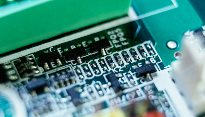
- SPI becomes the bottleneck. The MAC-PHY can receive and transmit at 10 Mbit/s simultaneously, while the host reaches it through one serial bus with framing overhead. The SPI clock, DMA support on the MCU and how the driver batches transfers decide whether the device keeps up during a burst. Bursts are normal: discovery traffic after a controller restart, multicast nobody asked for, an engineering tool scanning the segment.
- Filtering protects the host. MAC address filtering in the MAC-PHY means unwanted frames never cross the SPI bus. Configure it deliberately; a port left promiscuous during bring-up tends to stay that way.
- Priorities must match traffic. PROFINET real-time frames (EtherType 0x8892) should not queue behind an OPC UA browse response. The two hardware queues help only if the driver and network interface actually use them.
- The interrupt path is part of the timing budget. The RTOS task that services the MAC-PHY interrupt competes with sensor acquisition and protocol tasks. Measure the worst-case latency from frame arrival to stack delivery, not the average.
If a device needs to pass traffic to a neighbor, for example in SPE line topologies outside the APL trunk-and-spur model, a two-port device with an integrated switch, such as the ADIN2111, changes the architecture again. Decide that early, because it affects power and layout.
Power Budget Is a System Architecture Constraint
On a line-powered device, the port class is the hard ceiling and every function is a withdrawal from it. The budget has to close before schematic freeze, because the fixes for an overrun — a different MCU, a slower ADC, a dimmer display, another DC/DC topology — are board changes.
For orientation only: in the first generation of the port profile, the intrinsically safe spur power classes leave the field device in the region of 0.5 W to 1 W depending on class, according to an IEEE 802.3 ad hoc presentation by Pepperl+Fuchs. In November 2025 the standards organizations announced Power Class B for devices up to 1.16 W, incorporated into the second edition of IEC TS 63444. Take the binding values for your port class from the current specification, not from articles, this one included.
A budget worksheet that survives design reviews has these lines:
| Line item | What goes in it | Typical trap |
|---|---|---|
| Available at the port | Minimum guaranteed power for the selected port class at worst-case cable length | Using the nominal value instead of the minimum |
| Power interface losses | Polarity-tolerant input, inrush limiting, DC/DC efficiency at light load | Reading efficiency curves at full load |
| Communications | PHY or MAC-PHY in the selected transmit-level mode | Ignoring the difference between 1.0 V and 2.4 V operation |
| Compute and memory | MCU active and sleep current, external flash and RAM | Budgeting the average, not the protocol-stack peak |
| Sensing | Analog front end, excitation, reference, ADC | Excitation current that changes with sensor type |
| Local HMI | Display, backlight, LEDs | A display added late “for service” |
| Peak states | Startup, flash erase and write during update, cable diagnostics, sensor self-test | Peaks that coincide |
| Margin | Reserve for aging, temperature and future firmware | Zero margin at design freeze |
Peaks matter more than averages. A device that averages comfortably under its class can still brown out if a flash erase during an update overlaps with sensor excitation. Energy storage is the obvious fix, but in an intrinsically safe design stored energy is exactly what the Ex assessment scrutinizes, so the buffer cannot simply grow. Scheduling usually helps more: sequence the expensive operations so they never overlap.
Not every APL device is powered by the segment. Analyzers, actuators and instruments with heaters or large displays often keep a local supply and use Ethernet-APL only for communication; the port profile covers ports without power for this reason. A four-wire device gains headroom but brings its own isolation, grounding and Ex questions. Make the choice explicit in the architecture document.
For fitting such devices into an installed plant, see our guide to brownfield Ethernet-APL implementation planning.
Front-End, Coupling, Protection and PCB Layout
Link quality and APL conformance are properties of the port as built, not of the PHY alone. Most of what decides them sits between the connector and the PHY pins.
Coupling and Termination
The MDI network separates DC power from the data signal: power coupling inductors, signal coupling capacitors, termination and, usually, a common-mode choke. The ADIN1110 uses external termination resistors; its sibling, the ADIN1111, integrates the hybrid and termination. Start from the PHY vendor’s reference design and the port profile requirements, then re-verify every substitution. ADI’s vibration sensor design article shows how these components are modeled together. An inductor that saturates at spur current, or a capacitor that drifts with temperature, shows up as a link-quality problem months later.
Polarity
The PHY detects and corrects swapped data polarity. Power is a separate matter: a device that may be wired either way needs a polarity-tolerant power input, and the losses of that circuit belong in the power budget.
Surge, ESD and Burst Protection
Surge, ESD and fast transients arrive on the same two wires that carry data and power. Protection parts add capacitance and leakage to the line, so they interact with both signal integrity and intrinsic safety limits. The IEC 61000-4-x levels on a PHY product page describe the vendor’s test setup. Your enclosure, cable entry and bonding decide your result, so plan for pre-compliance testing instead of inheriting numbers.
Shield, Bonding and Isolation
Decide early how the cable shield terminates (the port profiles define shield connection options), where functional ground goes, and whether the port is galvanically isolated from the sensor and housing. In Ex i designs, segregation, creepage and clearance follow the intrinsic safety rules of IEC 60079-11 and directly constrain placement.
Measurement Integrity
The most expensive layout bug in a sensor is the one that corrupts the measurement. Keep the DC/DC converter, the SPI bus and the MDI network away from the analog front end and its reference, give the AFE its own return path, and check measurement noise with the link fully loaded, not idle.
Production Constraints
Industrial temperature range, long-lifecycle components with second sources where possible, test points for end-of-line testing, and a layout a contract manufacturer can build repeatedly. The ADIN1110 is offered in −40 °C to +85 °C and −40 °C to +105 °C grades; compare that with the real internal temperature of a sealed housing in the sun, not with ambient. This is where schematic and PCB layout decisions become production decisions.
Building or modernizing a field device for 10BASE-T1L or Ethernet-APL?
Firmware Architecture: Link Bring-Up Is Only the First Layer
A link LED proves the bottom of the stack. A field device needs all of it, built from the bottom up:
| Layer | What it has to do |
|---|---|
| 1. PHY / MAC-PHY driver | Initialization, transmit level, link state, error and statistics counters, cable diagnostics |
| 2. Network interface | Frame queues, priority mapping, MAC filters, the TCP/IP stack |
| 3. RTOS and BSP | Task priorities, memory pools, HAL and device drivers, watchdog |
| 4. Industrial protocol | PROFINET IO device: cyclic data, alarms, I&M data, GSDML; PA Profile where applicable |
| 5. Data access layer | OPC UA server and the device information model |
| 6. Device application | Measurement, signal processing, parameter handling |
| 7. Lifecycle services | Diagnostics, logging, firmware update and recovery |
- Driver. Bring-up means more than “link up”: transmit level configured for the port class, link changes reported upward, counters exposed, and a clear rule on whether cable diagnostics may run while a process connection is active.
- RTOS. With FreeRTOS or a similar kernel, allocate protocol memory statically where you can. Heap fragmentation in a device expected to run for years without a reboot is a bug that appears in month nine.
- PROFINET. The device must behave as a correct IO device: name assignment over DCP, application relationship setup and loss, cyclic data at the configured update time, diagnostic alarms, I&M data, and a GSDML file that matches the firmware. For process instruments, PI’s PA Profile 4 adds common parameters, NE 107-aligned diagnostics and automatic device replacement across manufacturers. PROFINET certification is a separate step with its own test cases; plan for it rather than assume it.
- OPC UA. OPC UA and PROFINET are not one stack. PROFINET carries cyclic process data to a controller; OPC UA exposes a browsable information model to engineering, asset-management or edge systems. An open62541-based server on an MCU needs hard limits on sessions, subscriptions, monitored items and certificate handling. Run both protocols together only when the CPU and RAM budget shows it, and test them under combined load.
- Update path. A bootloader such as MCUboot verifies image signatures and can swap in a new image with a revert path if the new image never confirms itself. Decide the slot layout, the confirmation rule — when does new firmware declare itself good? — and what happens if power drops mid-update on a spur. A device that bricks during an update means a site visit.
- Recovery and state. A hardware watchdog with a meaningful service policy, a recorded reset cause, power-fail-safe persistent configuration, and defined output behavior while the device restarts.
These layers are routine work for MCU firmware on RTOS and bare metal. What is not routine is making them share one small MCU for a decade.
Diagnostics Should Be Designed, Not Added Later
Ethernet gives a field device room to report far more than a current loop ever could. That only helps if the data model is designed for the people who consume it. Network diagnostics and process diagnostics have different owners: the OT network team cares about link quality, the instrument technician cares whether the measurement can be trusted.
| Diagnostic area | Examples | Primary consumer |
|---|---|---|
| Link and cable | Link history, MSE link quality, TDR cable fault location where the PHY supports it, error counters | OT network maintenance |
| Protocol and connection | Application relationship state, alarms raised and cleared, configuration mismatches | Control system engineers |
| Device health | Status mapped to NE 107: failure, function check, out of specification, maintenance required | Instrument technicians, asset management |
| Measurement | Sensor open or short, out of range, AFE self-test | Operators, maintenance |
| Lifecycle | Firmware version, update state, reset cause, uptime | Service and product support |
NE 107 is a status model, not a certificate. Use it where the target protocol and profile call for it, and map each internal fault to one category on purpose. A device that raises “maintenance required” for a cable fault and “failure” for a transient sensor glitch teaches operators to ignore it.
One decision is easy to postpone and expensive to change: what does the device report when the link degrades but does not drop? Trending the MSE value can warn before the link fails, but only if someone has decided where that warning goes.
Security and Lifecycle at the Field Level
Once a field device has an IP address, it has an attack surface a current loop never had. For a product that stays installed for a decade, security belongs in the embedded architecture. A reasonable baseline:
- Secure boot and signed firmware images, with keys that are not shared across the entire product line.
- Debug interfaces locked or disabled in production units.
- Protected storage for configuration and credentials.
- Certificate handling where the stack needs it: OPC UA application instance certificates, and the cryptographic PROFINET Security Classes 2 and 3 as controllers adopt them.
- Security event logging sized to what the device can actually afford.
IEC 62443 provides the framework: 62443-4-1 for the secure development process, 62443-4-2 for component security requirements. In the EU, the Cyber Resilience Act adds lifecycle obligations for products with digital elements, including vulnerability handling and security updates; its reporting obligations apply from September 2026 and its main requirements from December 2027. For a device team the consequence is concrete: the update path from the previous section is also a compliance mechanism. See embedded security engineering for how this is approached at the firmware level.

Validation: From Bench Link to Production-Ready Device
“Link up” is the first test, not the result. Validation works best as a ladder where each rung assumes the previous ones held.
| Stage | What is checked | Typical evidence |
|---|---|---|
| Architecture | Port profile, power class, Ex scope, protocol set and update strategy agreed | Design specification, power budget worksheet |
| Schematic and layout review | Coupling network against the reference design, protection, isolation and segregation, AFE separation | Review records, inputs for Ex documentation |
| Bring-up | Link stability across required cable lengths and types, transmit levels in use, polarity, error rates, MSE margin | Bench logs, cable test matrix |
| Power and thermal | Consumption in every operating state including peaks, behavior on a worst-case spur, internal temperature | Measurement report |
| Protocol and interoperability | Behavior against the target controller or DCS, not only a test tool; combined PROFINET and OPC UA load | Interoperability test report |
| Robustness | Update interrupted by power loss, link loss and recovery, watchdog paths, long-run tests | Test protocols, automated regression |
| EMC pre-compliance | Surge, burst, ESD and emissions in the real enclosure with the real cable entry | Pre-compliance report |
| Production readiness | Test points, end-of-line test, calibration, provisioning of identity and keys | Production test specification |
Certification files are assembled from this evidence: Ethernet-APL conformance testing, for which test cases and a test system have been developed as part of preparing the certification systems; protocol certification such as PROFINET; and Ex certification for intrinsically safe devices. Collecting the evidence as you go costs far less than reconstructing it at the end.
Regression on real hardware pays for itself here. For an industrial controller, Promwad built a two-layer Robot Framework suite that runs every firmware build on physical hardware inside an Azure DevOps CI/CD pipeline; see structured firmware QA for an industrial controller. The production end of the ladder is covered by in-production testing.
A Predictive-Maintenance Sensor on 10BASE-T1L With PROFINET and OPC UA
An Italian industrial equipment manufacturer needed a predictive-maintenance sensor that monitors vibration, friction, noise, heat, humidity and related parameters, and delivers that data over single-pair Ethernet into PROFINET and OPC UA environments.
Promwad integrated the Analog Devices ADIN1110 10BASE-T1L MAC-PHY with an STM32L496 microcontroller and built the embedded communication stack on top: FreeRTOS, PROFINET, an OPC UA data layer based on open62541, and MCUboot for firmware updates. The work ran from schematic through board bring-up to a working protocol stack.
The STM32L4 family has no on-chip Ethernet MAC, which is exactly the situation the MAC-PHY approach exists for. PROFINET and OPC UA are implemented as separate layers with separate roles, as described above. The project demonstrates the integration path; it is not presented as an Ethernet-APL certified product, since certification scope is decided per device.
- Client: Italian industrial equipment manufacturer
- MCU: STM32L496
- Physical layer: 10BASE-T1L
- MAC-PHY: Analog Devices ADIN1110
- Industrial protocol: PROFINET
- Data layer: OPC UA / open62541
- RTOS: FreeRTOS
- Firmware update: MCUboot
- Application: Predictive maintenance: vibration, friction, noise, heat, humidity and related parameters
The legacy side of the same transition shows up in other Promwad instrument work: an electromagnetic flow meter on STM32F7 with a DSP coprocessor that combines PROFINET, HART and Modbus RTU with an MCUboot bootloader, and an interface module upgrade with Modbus RTU and HART for Euromisure WIKA Italia.
Engineering scope and project context → Ethernet-APL & 10BASE-T1L Field Device Engineering
Practical Design Sequence
- Define the installation environment, power model and target protocols.
- Select the host MCU or SoC and decide between PHY and MAC-PHY.
- Close the power budget and interface architecture before schematic freeze.
- Design coupling, protection, grounding and shielding, and the PCB layout.
- Bring up the physical link and instrument diagnostics from day one.
- Integrate the RTOS, network interface and industrial protocol stack.
- Add diagnostics, update and recovery, and security mechanisms.
- Validate against the real controller or DCS and real network conditions, not only an evaluation board.
- Prepare production test and certification evidence early enough to avoid a late redesign.
Typical Ethernet-APL Field Device Engineering Tasks

Architecture and Compliance Scoping
Port profile, power class, Ex scope, protocol set and the PHY vs MAC-PHY decision, fixed before schematic capture.
Hardware Design and Bring-Up
MDI coupling, protection, power interface, AFE separation, and link validation across cable lengths and transmit levels.
Firmware and Protocol Integration
Drivers, RTOS, PROFINET, OPC UA, diagnostics, and MCUboot-based update and recovery on resource-limited MCUs.
Validation and Certification Preparation
Interoperability with the target system, robustness tests, EMC pre-compliance, production test, and evidence for conformance and certification.
You May Be Facing This If:
- ✓ The evaluation board links reliably, but your own board shows less link margin on the same cable.
- ✓ Measurement noise rises whenever the Ethernet link is busy.
- ✓ The device resets or browns out during firmware updates on a powered spur.
- ✓ PROFINET runs fine alone, but adding the OPC UA server causes missed cycles or memory exhaustion.
- ✓ Nobody can say which NE 107 status the device reports for a degraded cable.
- ✓ The power budget was last updated before the display was added.
- ✓ The certification plan is still “we will see what the test lab says.”
Real Trade-offs to Expect
- ✓ MAC-PHY on a low-power MCU vs PHY on a larger host. The MAC-PHY keeps power and BOM down and moves the complexity into the SPI driver and data path. A host with a native MAC handles traffic more comfortably but costs power the port class may not have.
- ✓ 1.0 V vs 2.4 V transmit level. Intrinsically safe APL spurs use the 1.0 V level, which also saves power; 2.4 V reaches further. In an APL device, the port profile usually decides, not preference.
- ✓ Two protocols vs one. PROFINET plus OPC UA widens market fit and doubles the validation surface and RAM pressure. One well-validated protocol often ships sooner.
- ✓ Energy storage vs Ex simplicity. More buffering rides through peaks, but stored energy complicates the intrinsic safety assessment. Sequencing loads is cheaper than arguing about capacitance.
- ✓ Rich diagnostics vs power and operator attention. Every diagnostic costs energy and someone’s attention. Report what a person or system will act on.
- ✓ Vendor reference design vs custom front end. The reference design shortens the path to conformance. Deviating from it can save cost or space, and every deviation has to be re-validated.
Where Device Design Becomes a System Architecture Problem
At this point the question is no longer which PHY to buy. It is how one small board shares a limited power budget, a single MCU, two protocol stacks, a measurement that must stay clean, and an update path that has to work for ten years in the field.
In practice, that means fixing the compliance boundary before the schematic, closing the power budget with peaks included, treating the SPI path and the coupling network as designed subsystems, separating PROFINET and OPC UA roles in firmware, designing diagnostics for their real consumers, and validating against the real control system. None of that is visible on an evaluation board, and all of it decides whether the product ships.
For the sensor side of the same work, see industrial sensor development; for the device-level connectivity scope, see Ethernet-APL & 10BASE-T1L field device engineering.
FAQ
Does using ADIN1110 make a device Ethernet-APL compliant?
When should I choose a PHY instead of a MAC-PHY?
Can PROFINET and OPC UA run in the same field device?
What usually causes late redesigns in an Ethernet-APL device?
Does adding Ethernet-APL require a new MCU?
How much power does an Ethernet-APL field device get?
Can Promwad certify an Ethernet-APL device?
Related Engineering Cases
- Ethernet-APL & 10BASE-T1L Field Device Engineering: MAC-PHY selection, PCB, firmware, PROFINET and OPC UA integration for field devices, including the ADIN1110-based predictive-maintenance sensor.
- Electromagnetic Flow Meter Design: STM32F7 with a DSP coprocessor, PROFINET, HART and Modbus RTU, MCUboot bootloader.
- Firmware Development for Industrial Protocols: interface module upgrade with Modbus RTU and HART integration for Euromisure WIKA Italia.
- Firmware QA for an Industrial Controller: a Robot Framework suite that runs every firmware build on real hardware in Azure DevOps CI/CD.
- Digital Twins Design for Control Loops: process and control-loop simulation across EtherCAT, PROFINET and EtherNet/IP on Xilinx Kria.
Tell Us About Your Ethernet-APL Field Device
Share the device type, power model, target protocols and where the project stands. We will help define the next engineering step.