



High-Speed PCB Design for Multi-Gigabit Interfaces
At multi-gigabit rates, the board itself becomes part of the circuit. A via stub, a gap in a reference plane or the wrong stack-up can close a DDR5 eye or break a PCIe Gen5 link, and the problem often appears only on the first prototype.
Promwad's high-speed PCB design starts with architecture: topology, stack-up and impedance are defined before routing, and every critical net is checked in pre- and post-layout analysis. Your board reaches bring-up with its margins already confirmed.

What's Included

Architecture and topology
Interface topology, clocking and termination are chosen with the SoC or FPGA vendor's guidelines and your mechanical limits in mind.
Stack-up and impedance planning
Layer count, materials and trace geometry are calculated with Polar and agreed with your PCB supplier before layout.
Constrained routing
Differential pairs, length and phase matching, via transitions and return-path control on every critical net.
Power delivery for high-current devices
Plane design, decoupling and sequencing for SoCs, FPGAs and memory with tight rail tolerances.
RF and mixed-signal sections
High-speed ADC/DAC front ends and RF paths placed and shielded next to fast digital logic.
Pre- and post-layout analysis
SI and PI checks at schematic and layout stages. How we run SI / PI / thermal analysis →
Interfaces and Form Factors We Design With
The same interface expertise runs through all our hardware design services, from carrier boards to complete systems.
DDR4, DDR5
PCIe Gen4/Gen5, 10/25/100GbE, MGBE, JESD204B
12G-SDI, MIPI CSI-2, CameraLink, HDMI, DisplayPort,
eDP, LVDS
PCIe cards, FMC (VITA 57.1), PCIe/104, PXIe, mini-PCIe, SoM and carrier boards, 1U systems
Our High-Speed Design Procedure
Twelve steps, with four review gates where a design does not move forward until it passes.
- Block diagram
- Design specification
- Library components review
- Schematic design
- Gate 1: schematic review by a firmware engineer
- Component placement
- Layer stack-up calculation
- Gate 2: pre-layout analysis of critical interfaces
- PCB routing
- Gate 3: PCB layout review against a high-speed checklist
- Gate 4: post-layout SI/PI analysis
- Design documentation
We own every step, so a tight schedule or a late requirement change is handled inside the procedure.
What You Receive
The full production package that comes with every Promwad PCB design project, plus the high-speed evidence behind it:

High-Speed PCB Case Studies
Hot-Swappable CFexpress Storage for FPGA Systems
Broadcasting · FMC HPC (VITA 57.1) · PCIe Gen3
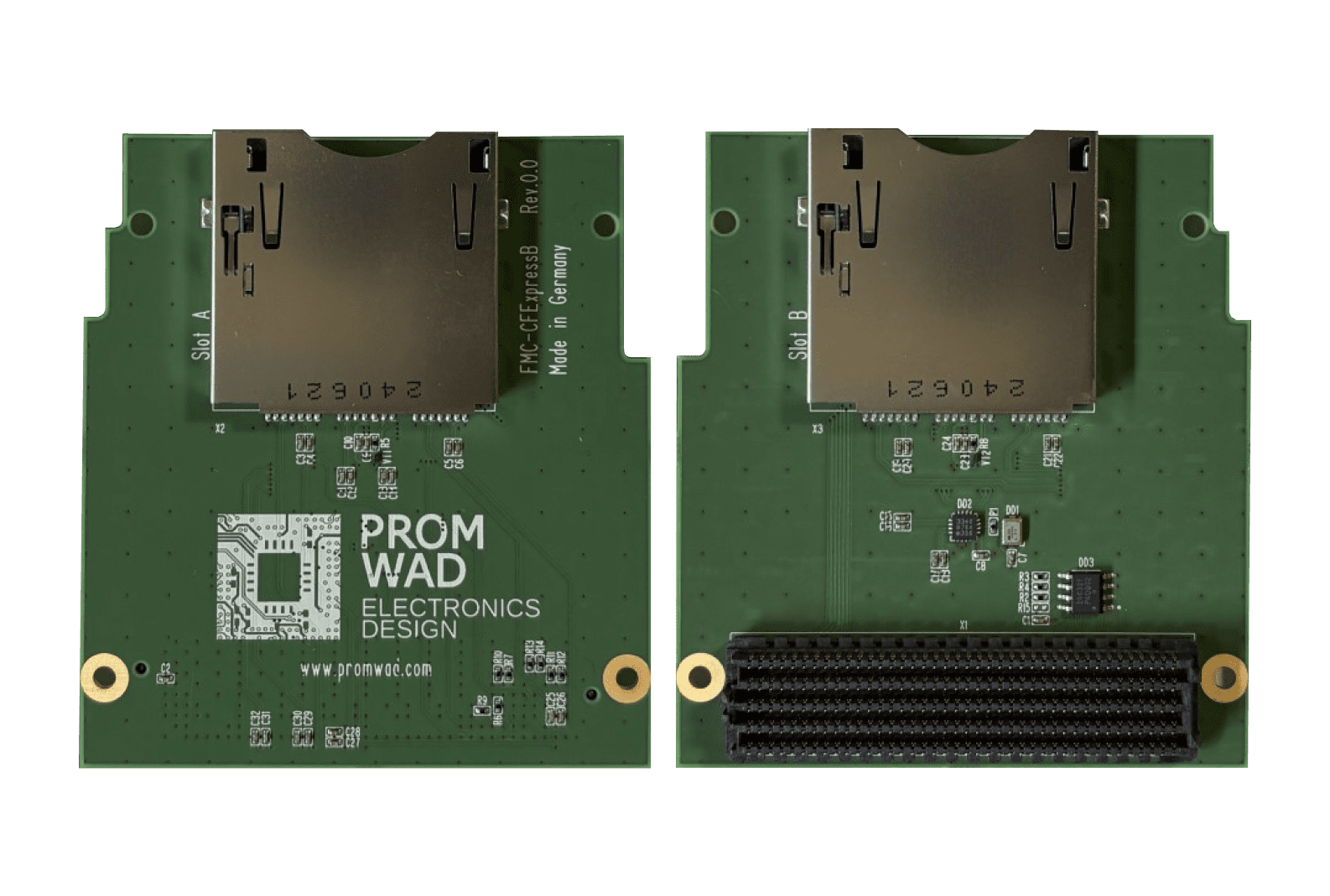
Pain. Angelbird, a provider of high-performance storage media, needed fast local storage for FPGA-based broadcast and video systems. It had to be high-throughput and low-latency, take removable media for instant offload, and connect directly to leading FPGA platforms.
Solution. We designed a CFexpress Type B storage board on the FMC HPC (VITA 57.1) standard. It runs two hot-swappable CFexpress Type B cards over PCIe Gen3 x2/x4 lanes, routed from the FMC connector to the card slots.
Result. The board is in commercial use for 12K+ RAW and high-frame-rate recording in OB vans, DIT stations and field kits. It has since found use in industrial storage and rugged data logging, and grew into a line of FMC storage boards.
Broadband SDR Satellite Modem in 1U
Telecom · AMD Zynq UltraScale+ · 4× 10G · High-speed ADC/DAC
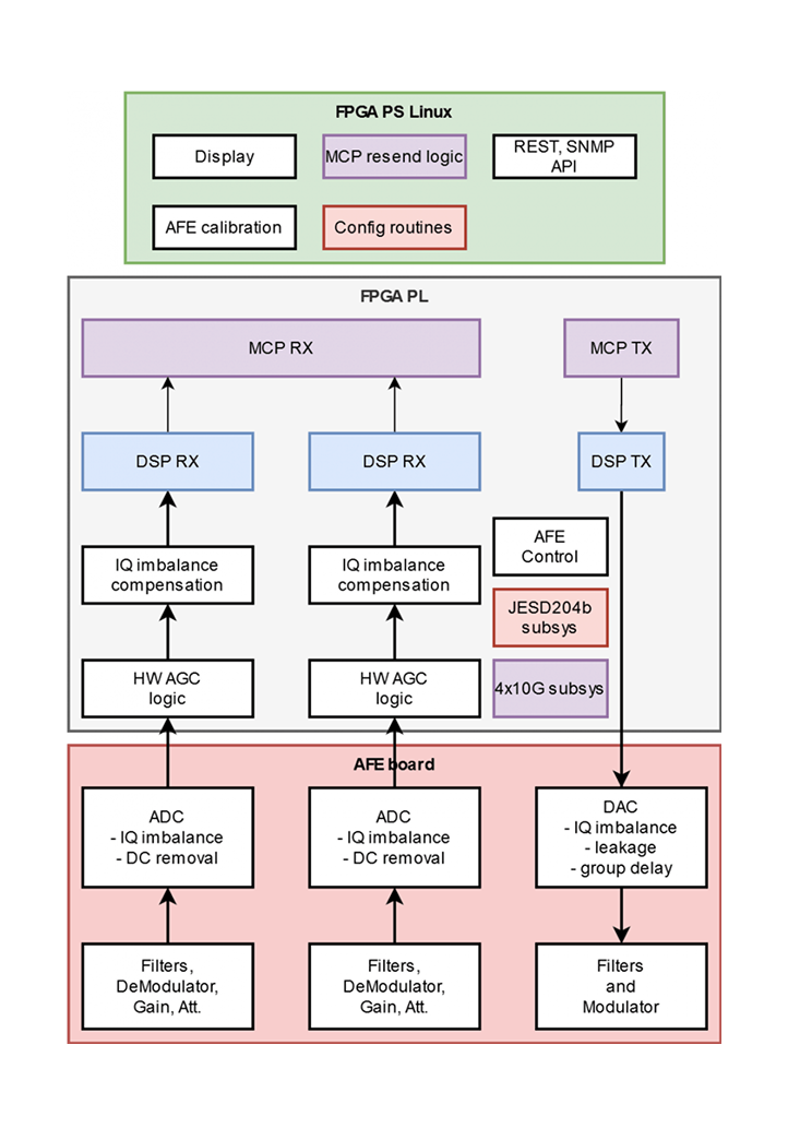
Pain. A European developer of ground-segment satellite software wanted its own branded hardware platform for a satellite modem, with room to scale functionality later.
Solution. We split the 1U device into a digital board on AMD Zynq UltraScale+ and an analog front-end board with high-speed ADC/DAC converters and high-frequency modulators and demodulators. Four 10G interfaces with DPDK carry data between the modem and the server.
Result. A flexible platform: to extend the modem's functions, the client repurposes only the analog front-end board while the high-speed digital board stays unchanged.
What Our Clients Say
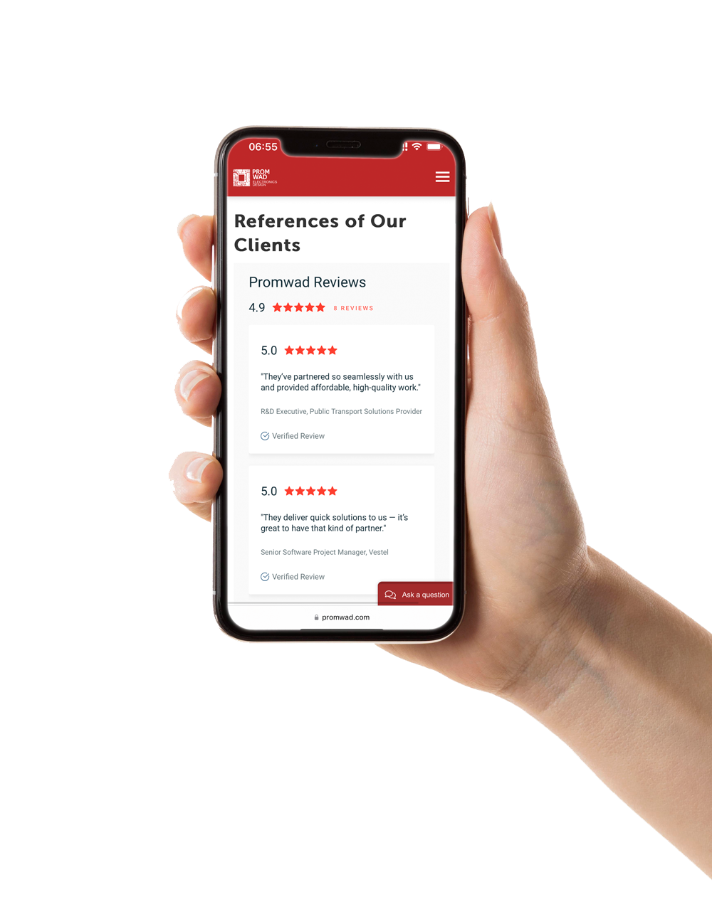
“Promwad completed the client's radio-electronic components research, schematics, schema, PCB design, and more. Their agile project management methodology impressed the client. The team was also flexible and has excellent leadership abilities.”

“Promwad has done a great job of managing their part in our projects. We've done 20–25 purchase orders, and worked on several projects with them. […] Their main strength is that they offer all the skills we need, such as mechanical design, firmware and software development, PCB layout, and schematic generation.”

Share Your Interface List and Constraints
Send us your block diagram, the high-speed interfaces on the board and your form-factor limits. Our engineers will come back with the risks they see and a proposed stack-up and design approach.
FAQ
When does a board need high-speed PCB design?
How do you choose the layer count and materials?
Can you fix a high-speed board that fails on the bench?
Do you work from SoC and FPGA vendor reference designs?
Can the same team handle FPGA and firmware for the board?