


Why a 360° Truck View Is Not Enough for BSIS, MOIS and London DVS Compliance
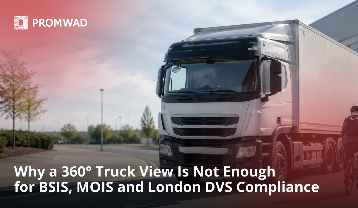
Consider a common failure pattern in heavy-vehicle surround-view development. Four fisheye cameras. A clean bird's-eye stitch on the cab display. In the depot the system looks finished — front, rear and both sides fused into one top-down image, the seams barely visible, the driver able to see the kerb, the trailer edge and the space behind the tailgate. The picture is good, and it is easy to conclude the hard part is done.
Take that system to vehicle-level validation, though, and three things can surface that the depot never had a way to expose.
A nearside camera catches road spray and a film of mud. The stitch does not go black — it keeps painting that quadrant from the last usable frame and blends it so smoothly that the composite looks whole while the real nearside is unseen.
The system has no automated warning function. It shows the driver a picture, but it does not detect the cyclist tracking up the nearside during a turn, does not flag the pedestrian standing in the front blind area as the truck pulls away, and cannot raise the information-then-warning escalation that UN R151 and R159 actually require.
And when a rear camera link drops for a few hundred milliseconds on a rough haul road, the display freezes rather than telling the driver a sensor has failed — the opposite of the failure warning the regulation demands.
Nothing about the stitching has "failed." The image quality is fine. The vehicle fails at the layer nobody treated as the hard part: turning a surround-view picture into a compliant, fault-aware detection-and-warning system.
Teams typically assume: if four cameras stitch into a clean 360° bird's-eye view on the cab display, the vehicle is essentially ready for BSIS, MOIS and Direct Vision compliance.
In reality: a stitched surround view is an indirect-vision aid for the driver. BSIS (UN R151) and MOIS (UN R159) require an automated detection-and-warning function with defined zones, signal timing, information/warning escalation and an explicit failure warning, while London's Direct Vision Standard may separately require the Progressive Safe System package for vehicles with insufficient direct vision — a separate engineering problem the stitch does not solve, and one a demo never stresses.
These gaps may only become visible during vehicle-level validation, approval testing or field operation.
Quick Overview
Problem: A 360° surround-view system that looks complete on the bench cannot, on its own, meet BSIS/MOIS or, where applicable, London PSS requirements or behave safely when a camera is degraded or lost.
Common causes: Treating stitching as detection, blind-zone geometry validated on paper only, uncalibrated or drifting extrinsics, latency measured for one stream instead of glass-to-glass, no silent-failure detection, and a validation plan that skips failure injection and environmental load.
Where it appears: N2/N3 trucks and M2/M3 buses under the EU General Safety Regulation, and HGVs entering Greater London under the Direct Vision Standard. The same engineering principles also apply to off-highway machines — construction, agricultural, forestry, mining and port equipment — with tall cabs and large occluded zones, although the regulatory framework that applies to them may differ.
Engineering focus: Blind-zone-driven camera placement, a detection path distinct from the view path, multi-camera calibration, a glass-to-glass latency budget, degraded-mode behavior with compliant failure warnings, and validation against regulation and real conditions — not a clean bench stitch.
Why a Clean Stitch Tells You Almost Nothing About Compliance
A surround-view demo is built to look finished. Four wide-angle cameras, a dry vehicle, even light, a short calibration on a flat depot floor, and a bird's-eye projection that fuses the feeds into one top-down image. Under those conditions the stitch is convincing, and that is the trap: the picture is the easy part, and the demo makes it look like the whole job.
The regulations do not ask for a picture. BSIS (UN R151) and MOIS (UN R159) ask for a system that detects vulnerable road users in specific zones, decides whether a collision is developing, escalates from an information signal to a warning signal on defined timing, and tells the driver when it can no longer see; London's Direct Vision Standard adds a separate fitment requirement, the Progressive Safe System, for vehicles with insufficient direct vision. Those are detection, decision and diagnostics functions. A stitched view delivers none of them by itself.
There are four places the real deployment pulls where the demo never does: the geometry of the blind zones, the split between showing and detecting, the timing budget from photons to pixels, and what the system does when a camera is dirty, shaken or dead. Take them in order.
Camera Placement Starts From the Blind Zone, Not the Vehicle
The mistake is to mount cameras where the bodywork allows and hope the coverage adds up. The discipline is the reverse: map the occluded volume around the vehicle first, then place cameras to cover it with margin.
A heavy truck's blind zones are not symmetric. The nearside — the side R151 calls the "near side" — carries the highest cyclist risk during turns. The close-proximity area directly ahead of a high cab is where MOIS scenarios happen when the vehicle moves off from rest. The offside and the trailer edges matter for lane changes and articulation. A tractor-trailer's blind geometry changes with articulation angle, so a fixed four-camera layout that covers the straight configuration can open a gap mid-turn — exactly when the cyclist is there.
Fisheye lenses (typically around a 180° field of view) let four to six cameras cover the full perimeter, but wide angle buys coverage at the cost of angular resolution at the edges, where a distant cyclist is only a few pixels tall. Placement trades three things against each other: overlap between adjacent cameras (needed for stitching and detection hand-off), effective resolution in the zones that carry regulatory weight, and mounting points that survive vibration and washdown. The output of this stage is not "four cameras on the corners"; it is a coverage map proving every regulated zone is seen by at least one camera, at usable resolution, across the vehicle's real range of motion. Mapping that coverage is the starting point for any heavy-vehicle camera layout — the domain of Promwad's vehicle vision and ADAS sensor work and its off-road and industrial vehicle engineering, where cab height and articulation make the occluded volume far larger than on a passenger car.
Two Different Jobs: Surround-View Stitching vs. Object Detection
This is the distinction that separates a demo from a compliant system, and it is worth stating plainly: stitching and detection are different pipelines that happen to share cameras.
Surround-view stitching takes the raw fisheye feeds, de-warps each one through its lens model, projects them onto a ground-plane or bowl surface, and blends the overlaps into a single bird's-eye or 3D view. Its job is presentation. Success is measured in seam quality, geometric consistency and how intuitive the composited view is — indirect vision, the same category of function a camera monitor system / digital mirror provides.
Object detection is a separate perception pipeline — typically a neural network running per-camera or on a fused representation — whose job is to find and classify vulnerable road users, place them in the vehicle frame, track them across frames, and give a decision layer enough to judge whether a BSIS or MOIS event is developing. Success is measured in detection rate, false-positive rate, latency and zone accuracy. This is the layer that actually satisfies R151 and R159, and it is the layer a stitch quietly skips.
Conflating the two produces the most common failure in this space: a system that shows a beautiful surround view and believes it is therefore "seeing" the cyclist. It is not. The pixels are on the screen; nothing has decided they are a person on a bike inside the warning zone. Building that detection path means edge computer vision running inside the vehicle's power and thermal budget — the kind of work behind Promwad's ADAS development and edge-AI engineering, including embedded computer-vision hardware such as a camera module built on the Ambarella CV25 SoC. A production BSIS/MOIS perception function would still require dedicated datasets, models and vehicle-level validation on top of that hardware experience.
What BSIS, MOIS and Direct Vision Actually Require
Three regimes, one vehicle, and they do not ask for the same thing.
BSIS — Blind Spot Information System, UN Regulation No. 151. A system that informs the driver of a possible collision with a cyclist on the near side, primarily during turning manoeuvres. R151 defines two escalating signals: an information signal that is noticeable but not alarming, and a warning signal — differing in mode or activation strategy — raised when the collision risk becomes real, for example when the turn indicator is active and a trajectory intersection is predicted. It also requires a failure warning: a yellow optical signal, distinct from the information signal, when the system is degraded or unavailable. In force since 2019; mandatory for new registrations of M2, M3, N2 and N3 vehicles from 7 July 2024.
MOIS — Moving Off Information System, UN Regulation No. 159. A forward-looking function that detects pedestrians and cyclists in the close-proximity blind area directly in front of the cab and warns the driver as the vehicle moves off from rest — the classic pull-away-at-the-lights collision. Same regulatory family and the same information/warning logic, but a different zone and a different triggering condition.
Direct Vision — the Transport for London Direct Vision Standard. Not a detection spec but a visibility spec: HGVs over 12 tonnes are rated zero to five stars for how much the driver can see directly through the cab glass, and the rating is fixed at manufacture. From 28 October 2024 the minimum is three stars; anything below must fit the Progressive Safe System (PSS) to earn an HGV Safety Permit for Greater London — and the PSS package includes a nearside camera monitoring system, Class V and VI mirrors or a compliant replacement CMS, a nearside BSIS, a front MOIS, side under-run protection, an audible manoeuvring warning and external warning signage. Non-compliance carries a penalty of up to £550 per day. TfL treats vehicles approved to R151 and R159 as meeting the BSIS/MOIS part of the PSS.
Under all of it in the EU sits the General Safety Regulation (EU) 2019/2144, which mandates blind-spot and moving-off protection for heavy vehicles, and UN Regulation No. 46, which governs the camera monitor systems used for mirror replacement and the nearside CMS in a PSS. The practical consequence for an engineering team: an HGV may need an R46-compliant camera monitoring system alongside separate BSIS and MOIS functions, coordinated within a shared vehicle architecture. These functions may reuse some sensors and compute resources, but do not have to rely on the same cameras.
Multi-Camera Calibration Is Where the Geometry Lives or Dies
Every claim the system makes about where an object is — which zone a cyclist is in, whether the bird's-eye view is metrically honest — rests on calibration.
There are two layers. Intrinsic calibration models each lens: for fisheye optics, an equidistant or equisolid projection with distortion terms (the OpenCV fisheye or Kannala-Brandt model), so a pixel maps to a bearing. Extrinsic calibration fixes each camera's pose — position and orientation — relative to a common vehicle coordinate frame, so the four bearings resolve into one consistent ground plane. Get the extrinsics wrong by a couple of degrees and the seams misalign and, worse, the detection layer places a cyclist in the wrong zone.
The hard part is that extrinsics do not stay put. A door-mounted camera moves when the door opens; a mirror-arm camera shifts on its mount; suspension load, thermal expansion and years of vibration all drift the pose. Factory calibration against targets is necessary but not sufficient. Depending on mounting stability and the safety concept, a production heavy-vehicle system may need drift monitoring, service recalibration, or validated online, targetless recalibration that uses scene structure and vehicle motion to detect and correct drift, plus a way to flag when drift exceeds what recalibration can absorb. Camera calibration and sensor integration of this kind sit inside Promwad's ADAS sensor work, and they are unforgiving on articulated and off-highway machines whose cameras ride on structures that move relative to each other by design.
The Latency Budget: From Photons to a Warning the Driver Can Use
Latency in a surround-view system is not one number; it is a chain, and every link spends part of a fixed budget. Walk the path of a single frame:
sensor exposure + readout → ISP (de-Bayer, HDR tone-mapping, LED-flicker mitigation) → serial transport (GMSL/FPD-Link or automotive Ethernet) → de-warp + stitch, plus per-camera detection → compositing → display panel
Glass-to-glass latency — photons at the lens to photons at the display — is what a mirror-replacement CMS is actually judged on, and it is an explicit, tested parameter under UN R46 / ISO 16505, not an afterthought. At 30 fps each frame is a 33 ms slot; at 60 fps, 16.7 ms. Capture and ISP alone can eat one to two frames; a naive stitch adds another; a detection network adds its own inference time; and any stage that buffers to smooth jitter is latency you pay every frame. A design that hits its average on the bench can still blow the budget under load — exactly as a pipeline that meets its model-inference target in isolation misses end-to-end, the failure mode dissected in Promwad's write-up on why AI inference latency fails in production.
For the detection path there is a second, harder clock. TfL's PSS specification uses a driver reaction-time assumption of roughly 1.4 seconds when defining early-information timing, which means the system must detect, classify, decide and escalate from information to warning early enough that the human still has that reaction window. Detection latency here is not a comfort metric; it is the difference between a warning that helps and one that arrives after the collision point.
Dirt, Water, Vibration and Glare — and the Silent-Failure Trap
Passenger-car surround-view lives a gentle life compared with a construction truck or a forestry machine. Heavy and off-highway vehicles subject the cameras to washdown, road spray, mud, dust ingress, condensation, constant vibration, thermal cycling and direct low-sun glare — and each one attacks a different part of the pipeline.
Water and mud are the dangerous ones because of how stitching hides them. A lens caked in spray does not produce a black frame; it produces a low-contrast, plausible frame that the blender folds happily into the composite. The driver sees a complete bird's-eye view with one quadrant that is quietly blind. This is why sealing (IP69K for high-pressure washdown), hydrophobic coatings and, on many builds, lens heaters are not accessories — they protect the input the whole safety case depends on. Vibration attacks calibration: resonance at the mounting point walks the extrinsics off true, degrading both the seam and the zone accuracy. Glare and LED-lit road users attack the sensor: without high-dynamic-range capture and LED-flicker mitigation, a cyclist under a low sun or beside a flickering signal can wash out or strobe out of frame at the moment detection matters most. The engineering answer is partly optical and mechanical, partly a health-monitoring layer that measures per-camera contrast, sharpness and blockage and treats a degraded input as a fault — which is what turns the silent-failure trap into a compliant failure warning. That environmental and enclosure discipline is part of Promwad's construction, agricultural and forestry vehicle work.
When a Camera Dies: Degraded Modes and the Failure Warning
A four-camera surround system has four single points of failure, and the regulations care about all of them.
The failure that matters most is the quiet one. If a camera link drops, freezes, or the lens is blinded, a naive stitch keeps rendering that region from stale data or blends the gap so the composite still looks whole. That is the worst possible behavior: it hands the driver a confident, complete-looking view of a region the system can no longer see. R151 and R46 both require the opposite — an explicit, driver-visible indication that the system is degraded, the R151 failure warning being a yellow optical signal distinct from normal information.
A production-grade system therefore needs a health monitor running alongside the pipeline that continuously answers "is each camera delivering usable frames?" — checking link integrity, frame freshness (a frozen feed is a failure even though frames keep arriving) and image quality. On loss it must degrade gracefully and honestly: suppress stale or invalid image regions rather than fake them, clearly identify which functions are unavailable, disable the detection zones that depended on the lost camera, and transition to a defined degraded state that raises the failure warning so the driver knows which capability is gone — the exact behavior following from the system safety concept. Designing that fault logic — detection, safe state and driver notification — is functional-safety work, the ISO 26262 ASIL discipline Promwad applies in its ASPICE and automotive software engineering and ECU platform practices.
The Driver HMI: Showing the Right Thing at the Right Moment
The system can be geometrically perfect and still fail the human. A 360° platform generates far more than a driver can watch, so the HMI's job is to show the right view and the right alert at the right moment, and to stay quiet otherwise. Context should drive the display: reverse gear brings up the rear and bird's-eye view; the nearside indicator brings up the nearside camera and BSIS zone; moving off from rest arms MOIS. The R151 signal hierarchy has to be legible in the cab — the information signal noticeable but not startling, the warning signal unmistakably more urgent, the failure warning distinct from both. The enemy is alert fatigue: a BSIS that fires on parked cars and roadside furniture trains the driver to ignore it, which is why detection quality and HMI design are the same safety problem, not two. Placement matters too — a display that pulls the driver's eyes far off the road trades one risk for another, so legibility and mounting position are part of the safety case. This is the human-factors and display-integration work in Promwad's HMI design for commercial and public-transport vehicles practice.
The Validation Plan: Prove It Where the Demo Didn't
Everything above converges on one question: how do you show the system works when the depot demo proves almost nothing? A credible validation plan has four layers.
Regulatory type-approval testing. The R151 dynamic and static bicycle scenarios and the R159 moving-off pedestrian scenarios, run against the defined zones, signal timing and failure-warning behavior — for the correct vehicle category (N2/N3, M2/M3) and, for London, against the DVS PSS fitment checklist.
System-level engineering validation. Calibration accuracy across the vehicle's range of motion (including articulation), glass-to-glass and detection latency measured under load rather than at idle, and detection performance characterized as rate and false-positive rate across VRU types, distances and lighting.
Environmental and durability. Thermal cycling, IP sealing under washdown, vibration to the relevant automotive and off-highway profiles, EMC, and low-sun/HDR/LED-flicker scenes — the conditions that separate a passenger-car build from one that survives a construction site or a forestry track.
Failure injection. Deliberately blind, freeze, drop and mud-cover each camera and confirm the system detects it, degrades honestly and raises the correct failure warning — the test the opening story failed. If a validation plan does not include camera-failure injection under load, that omission is usually where the field findings come from. Promwad's 360° camera modernisation included unit, integration, HIL and system-level testing within an ASPICE CL2 and ASIL-B-oriented development process. Environmental, contamination and BSIS/MOIS type-approval testing would require a dedicated validation scope.
Promwad Engineering Example: Modernizing an Automotive 360° Camera Platform
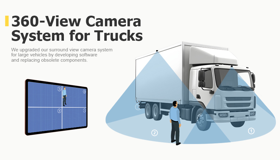
A supplier of rearview/side mirrors and camera-based vision systems came to Promwad with a 360° surround-view product that had become unbuildable: key components were discontinued, creating vendor lock-in, and the software stack needed to meet automotive process and safety targets rather than just produce a picture.
Promwad reworked the system around a Lattice CrossLink-NX FPGA for the video path and an NXP S32K228 MCU handling CAN communication with the vehicle, power management and driver interaction — replacing the obsolete parts and removing the lock-in. Critically, the development process was organised to ASPICE Capability Level 2, while the system was engineered to ISO 26262 ASIL-B requirements — the process and functional-safety framework such a deployment must satisfy alongside the type-approval requirements of the applicable regulations, rather than just producing the surround-view image.
The project demonstrates Promwad's experience in automotive-grade multi-camera electronics, structured ASPICE development and ISO 26262-oriented safety engineering — a multi-camera platform developed to an ASPICE CL2 process and engineered to ISO 26262 ASIL-B rather than left as a picture. Adding a certifiable BSIS/MOIS detection function and UNECE type-approval work would build on these competencies through a dedicated project scope and validation programme.
Full engineering write-up — the FPGA/MCU architecture, CAN integration and the ASPICE/ASIL work: → 360-Degree Truck Camera System (Spherical Camera System Design)
What This Approach Gives Fleet and Vehicle OEMs
The business value follows directly from separating "it shows a view" from "it is a safety function." A modular vehicle-vision and sensing architecture can be designed to support R46, R151, R159 and London PSS requirements without developing completely independent systems for each target market. Compliance risk drops because detection, latency, calibration and failure behavior are engineered and validated against the requirements and under real load, not assumed from a bench stitch. Component obsolescence stops being an existential threat when the architecture is designed to be re-hosted, as the 360°-camera case above shows. And the same platform can extend across the fleet — trucks, buses and off-highway machines — because the hard parts (blind-zone coverage, detection, degraded-mode safety) are shared, while the vehicle-specific layout changes on top.
When You Need This Approach
- You have a 360° surround view that looks finished but no automated BSIS/MOIS detection-and-warning function behind it.
- You need a single vehicle-vision architecture to satisfy R151, R159, UN R46 and the London DVS Progressive Safe System at the same time.
- Your system shows a plausible view when a camera is dirty or dead, instead of warning the driver.
- Your vehicles are trucks, buses or off-highway machines where cab height and articulation make the blind zones large and asymmetric.
- Your latency, calibration and detection numbers came from a bench, not from the vehicle under load.
How Promwad Helps
- Camera placement and blind-zone coverage analysis for trucks, buses and off-highway machines.
- Surround-view and video processing on FPGA/SoC — as in the 360° truck-camera platform (Lattice CrossLink-NX FPGA, NXP S32K228 MCU).
- Embedded vision hardware and on-device inference integration, building on our edge-AI work. Road-user detection models, datasets and vehicle-level validation are defined as a dedicated project scope.
- Sensor integration and calibration workflow development.
- Camera monitor systems and digital mirrors under UN R46, and engineering support for the London DVS Progressive Safe System.
- Functional safety to ISO 26262 (ASIL) and ASPICE process, including degraded-mode and failure-warning logic.
- Validation planning, HIL and system-level testing, with environmental and camera-failure testing included where required by the project scope.
Building or retrofitting 360° vision for heavy or off-highway vehicles?
Promwad can review your architecture, find the gap between "it stitches" and "it complies," and define a practical path from a surround-view picture to a compliant safety function.
FAQ
Is a 360° surround-view system enough to meet BSIS and MOIS?
What is the difference between BSIS (R151) and MOIS (R159)?
Does the Direct Vision Standard require cameras?
Why does a dirty or failed camera make a stitched view dangerous?
What latency does a truck camera system have to hit?
Can Promwad help if our surround-view product already exists but can't meet BSIS/MOIS or DVS?
Related Promwad Expertise
- 360-Degree Truck Camera System (Spherical Camera System Design) — the case behind this article: Lattice CrossLink-NX FPGA + NXP S32K228 MCU, CAN integration, ASPICE CL2 and ISO 26262 ASIL-B.
- Automotive Vision Systems & ADAS Sensors — camera and vision platforms for trucks, commercial and off-highway vehicles.
- ADAS Development — sensor fusion, VRU detection and functional-safety-driven ADAS engineering.
- Digital Mirrors & Camera Monitor Systems — CMS, SVM and mirror-replacement work under UN R46 / ISO 16505.
- Off-Road & Industrial Vehicle Solutions — vision and electronics for construction, agricultural and forestry machines.
- ASPICE & Automotive Software Engineering — the process and functional-safety framework behind safety-critical automotive systems.