


Debugging Mechatronic Failures Across Mechanics, Electronics, and Firmware
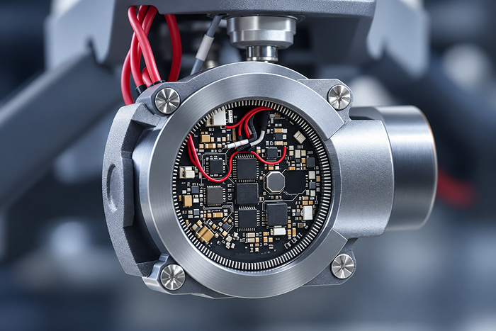
A motion axis overshoots on reversal. The firmware team patches the fault; the fix holds on the bench and returns in the field. A second patch narrows the window; the fault reappears under a different payload. Somewhere in the next iteration, someone asks whether the coupling has play — and the debug direction changes.
This is a common pattern in mechatronic products. The symptom is visible where the instrumentation is best — typically the firmware log — and the cause frequently lives one or two layers deeper, in mechanics, sensing, or the power stage. Treating the visible layer as the responsible layer is where projects lose time.
This article covers why interface failures are hard to isolate, five mechanisms that recurrently present as firmware defects, and a symptom-led diagnostic method that keeps competing hypotheses in view instead of committing to a single discipline too early. Nothing here substitutes for measurement on a specific system; the goal is to shorten the path to the measurement that changes the diagnosis.
Teams typically assume: if a fault appears in the control layer, the fault lives in the control layer.
In reality: in a mechatronic product the symptom is visible where the instrumentation is best. The cause is a separate question that can only be settled with synchronized measurements across disciplines.
Quick Overview
Problem: An intermittent mechatronic fault is triaged as a firmware issue because the log is the most searchable data source. Firmware patches modify the symptom without addressing the underlying mechanism.
Common mechanisms: Backlash and coupling compliance, structural or drivetrain resonance, sensor placement or observability limits, power-integrity issues on shared rails or grounds, and thermal drift of motor and sensor parameters.
Where it appears: Motion products across industrial automation, robotic arms, camera stabilization, consumer motion devices, and medical automation.
Engineering focus: A synchronized evidence set across encoder, current, rail, and temperature; a symptom-led investigation that keeps competing hypotheses in view; measurable, cross-discipline acceptance criteria.
Why Interface Failures Are Hard to Isolate
Three properties of firmware make it the default suspect, none of which are about firmware quality.
Visibility. Firmware writes logs. Logs are searchable and comparable across runs. Physical subsystems produce data only when explicitly instrumented, and that instrumentation is often absent on a product returning from the field.
Access. Firmware changes ship in hours; mechanical or PCB changes take days to weeks. The team that can respond fastest is asked first.
Reproducibility asymmetry. Firmware behavior is often easier to instrument and reproduce than intermittent mechanical, thermal, or power-related effects. That said, timing-dependent software faults — races, interrupt priority inversions, DMA contention, uninitialized state — remain in the hypothesis set. "We cannot reproduce it in firmware" is not evidence that it is not firmware; it is a reason to instrument what is running when the fault appears.
The visibility of a symptom in a discipline is not evidence of its cause. This is the reasoning that underpins integrated mechatronics engineering: mechanics, sensing, electronics, and firmware developed as one delivery instead of three sequential workstreams that meet at integration.
Build a Synchronized Evidence Set
Before diagnosing, capture. In most stuck debug sessions, the signal that would resolve the fault is the one nobody recorded.
Minimum evidence set for a mechatronic motion fault:
- Commanded setpoint (position or velocity).
- Position feedback (encoder or resolver reading), motor-side and, where feasible, load-side.
- Motor phase current.
- Controller supply rail (Vcc) and, where relevant, drive DC-link voltage.
- Board and motor temperature.
- Reset events and state transitions.
All channels time-aligned to the same clock. Without common timestamps, correlation across signals becomes guesswork.
Measurement safety note. Scoping a motor drive's supply rail or ground reference is not a benign measurement. A grounded oscilloscope input across a switching power stage can short the drive's return path, damage the instrument, or injure the operator. Use isolated or differential probes with appropriate CAT rating and voltage/bandwidth specifications; see Tektronix — Fundamentals of Floating Measurements and Isolated-Input Oscilloscopes. This is not a step to improvise.

Five Mechanisms That Present as Firmware Defects
Each mechanism below is described with the same five items: the observable symptom, competing hypotheses to keep open, a discriminating test, a common measurement mistake, and possible remedies. The aim is a short list of hypotheses per symptom — not a single answer.
1. Backlash and Mechanical Play
Observable symptom: Position error at reversal; hysteresis in the response.
Competing hypotheses: Coupling or gearbox backlash, drivetrain compliance, controller integral term behavior at reversal, drive dead-band.
Discriminating test: Open-loop step reversal with an independent load-side measurement. If load reversal lags motor-side reversal by a repeatable angle that does not respond to controller changes, backlash is present.
Common measurement mistake: Recording only the motor-side encoder, which by construction cannot see load-side compliance or coupling play.
Possible remedies: Preloaded or backlash-free coupling, load-side encoder, or feed-forward compensation where a mechanical fix is not practical. Compensation moves the fault into the model; it does not remove it.
2. Structural or Drivetrain Resonance
Observable symptom: Narrow-band oscillation, often at a frequency unrelated to control-loop timing; instability that appears at specific speeds or payloads.
Competing hypotheses: Structural mode near the control bandwidth, drivetrain compliance, filter phase lag reducing stability margin, or excess controller gain against the plant.
Discriminating test: Frequency response of the plant (swept-sine or broadband excitation) with the position loop open. Modal FEA locates expected modes before hardware exists; measurement confirms them.
Common measurement mistake: Concluding a resonance from a single time-domain oscillogram without a frequency response.
Possible remedies: A well-designed notch filter can attenuate a known resonant peak — this is standard motion-control practice for lightly damped modes; see, for example, MathWorks — Suppress Resonances Using Adaptive Notch Filter. A notch requires validation of bandwidth, phase margin impact, payload variation, and interaction with other loop dynamics. Structural stiffening or a lower control bandwidth are alternatives where a notch cannot cover the operating envelope.
3. Sensor Placement and Observability
Observable symptom: Persistent tracking bias; behavior that changes with mechanical repositioning or a different mount torque; the controller acts on data that is arithmetically correct but does not reflect what the loop needs to know.
Competing hypotheses: Sensor at the wrong location (motor-side vs load-side), sample rate too low relative to plant bandwidth, anti-aliasing filter phase lag, sensor bias or scale calibration drift, or mechanical decoupling between the sensor mount and the measured element.
Discriminating test: Independent measurement at the physical point the controller cares about, under the failing operating condition.
Common measurement mistake: Assuming a sensor "measures what it measures" without checking its transfer function, its mount rigidity, or its Nyquist relationship to the fastest mechanical dynamic present.
Possible remedies: Relocate the sensor, add a load-side sensor, tighten the mount, adjust the anti-aliasing filter, or reconstruct the missing signal from other measurements.
4. Power Integrity: Brownouts, Ground Bounce, EMI
Observable symptom: Unexplained resets, ADC readings shifting with drive activity, watchdog triggers correlated with motor load or regenerative braking.
Competing hypotheses: Shared return under a poor grounding topology, supply undersized for peak transient load, drive PWM coupling into sensor cables, brown-out below MCU minimum, EMI-induced ADC error, or decoupling network insufficient for the switching harmonics.
Discriminating test: Time-aligned scope of Vcc, ground reference (with isolated or differential probes — see safety note above), and drive activity during a failing cycle.
Common measurement mistake: A grounded scope on the drive side shorting the return; misinterpreting scope-induced noise as the fault under investigation.
Possible remedies: Star grounding, rail resizing, snubber or gate damping on switching edges, ferrites on sensor cables, and redesign of the decoupling network. These decisions are made most cheaply during mechatronics design and verification, when the drive stage and control board are treated as one electrical system rather than joined at a connector.
5. Thermal Drift
Observable symptom: Behavior fine at cold start; degrades after operating time; calibration values that need to differ between start-of-shift and mid-shift.
Competing hypotheses: Motor torque constant (Kt) drift with rotor temperature; bearing preload change with expansion; shunt resistor TCR; sensor bias drift; MOSFET Rds(on) rise reducing available current; passive component drift on the control board.
Discriminating test: Repeat the failing cycle from cold and from thermally soaked conditions, with board and motor temperature logged alongside the control error.
Common measurement mistake: Logging only ambient or enclosure temperature, which lags the temperatures the loop is actually sensitive to (rotor, junction, sensor die).
Possible remedies: Temperature-compensated calibration, low-TCR components in critical paths, revised thermal design of the enclosure, or online parameter estimation.
A Symptom-Led Diagnostic Sequence
The order in which hypotheses are tested depends on the symptom. A single fixed sequence does not fit every fault, and starting in the wrong place burns weeks. A short matrix, matched to the fault signature, is more useful than a universal recipe.
| Symptom | Where to look first |
| Resets or corrupted state | Supply rail, grounding topology, EMC coupling, reset line |
| Error at reversal | Backlash, coupling compliance, controller integral behavior |
| Narrow-band oscillation | Plant frequency response, mechanical modes, loop stability margins |
| Fault after warm-up | Temperature-correlated measurements, thermal profile of the axis |
| Fault only under load | Motor current, torque, supply transient, mechanical transmission |
| Fault only under multi-axis operation | Cross-axis coupling, shared rails, EMI, control interleaving |
Two rules hold across symptoms:
- Capture before hypothesizing. A hypothesis without synchronized evidence is a guess with more words. Instrument first; interpret second.
- Test inside a safe operating envelope. Open-loop excitation and frequency sweeps can drive an axis into a hard stop or over a current limit. Bounds on speed, current, and travel — and a documented risk assessment — come before the test.
Verification, Validation, and Acceptance Criteria

What can be verified without hardware
Static stiffness, natural frequencies via modal FEA, thermal steady state at rated load, worst-case supply transient behavior (SPICE), and closed-loop stability margins against a plant model. These reduce the risk of finding a mechanical or electrical limitation only after tooling.
What must be validated on physical prototype
Actual sensor noise floors, real backlash and friction, EMI on the harness, thermal transient response, control margin under actual payload variance, and behavior across the duty cycle the system will see in the field. Simulation narrows the search; it does not eliminate the physical measurement.
Acceptance criteria must cross disciplines
They should also be measurable. For example: closed-loop step response with defined payload and ambient temperature, following error below a stated bound, sustained across a stated number of cycles. Criteria expressed only inside one discipline, such as 'no firmware log errors,' do not close a fault that crossed disciplines.
Pre-compliance testing follows validation
Certification of the finished product is a separate track: Promwad supports pre-compliance testing and documentation but does not submit for certification on the client side.
When to Involve a Cross-Domain Engineering Team
Interface failures are resolved by measurement, not by argument between disciplines. Where a project does not have simultaneous access to mechanical, electronics, firmware, and simulation capability — or where the vendor who built the original product is unavailable — the practical alternative is system-level mechatronics development that treats these as one delivery. This covers the path from feasibility and modal analysis through prototype, verification, and production transfer, and includes modernization of existing products.
Once the root cause is understood, the next question is whether the fix should stay local or become part of a broader product update. For modernization of existing mechatronic products, that decision depends on which mechanical, electrical, firmware, test, and compliance dependencies the change reaches — and whether the right scope is a component replacement, a partial redesign, or a new architecture.
For an example of a Promwad mechatronic development where the mechanical constraints of the drive shaped the firmware and verification work rather than the other way around, see Turnkey Design for a Studio-Grade Direct-Drive Turntable.
Fault that keeps returning after each firmware patch?
FAQ
How Do We Distinguish a Control-Software Fault from a Mechanical Resonance?
What Should Be Measured When Resets Occur Only Under Motor Load?
When Is System-Level Simulation Justified?
Related Engineering Cases
- Turnkey Design for a Studio-Grade Direct-Drive Turntable: a mechatronic project where mechanical constraints of the drive shaped the firmware and verification design.
- Delta Robot Design for Conveyors: multi-axis mechatronics integrating mechanics, motion control, and machine vision.
- Custom Servo Drives for Conveyors: power stage, control, and mechanical integration in an industrial motion product.
Tell Us About Your Mechatronic Product
Share the product type, the fault signature, and where the current debugging has stalled. We will help define the next engineering step from repeat failure to root cause.