


Legacy Mechatronic Product Modernization: What to Keep, Replace, or Redesign
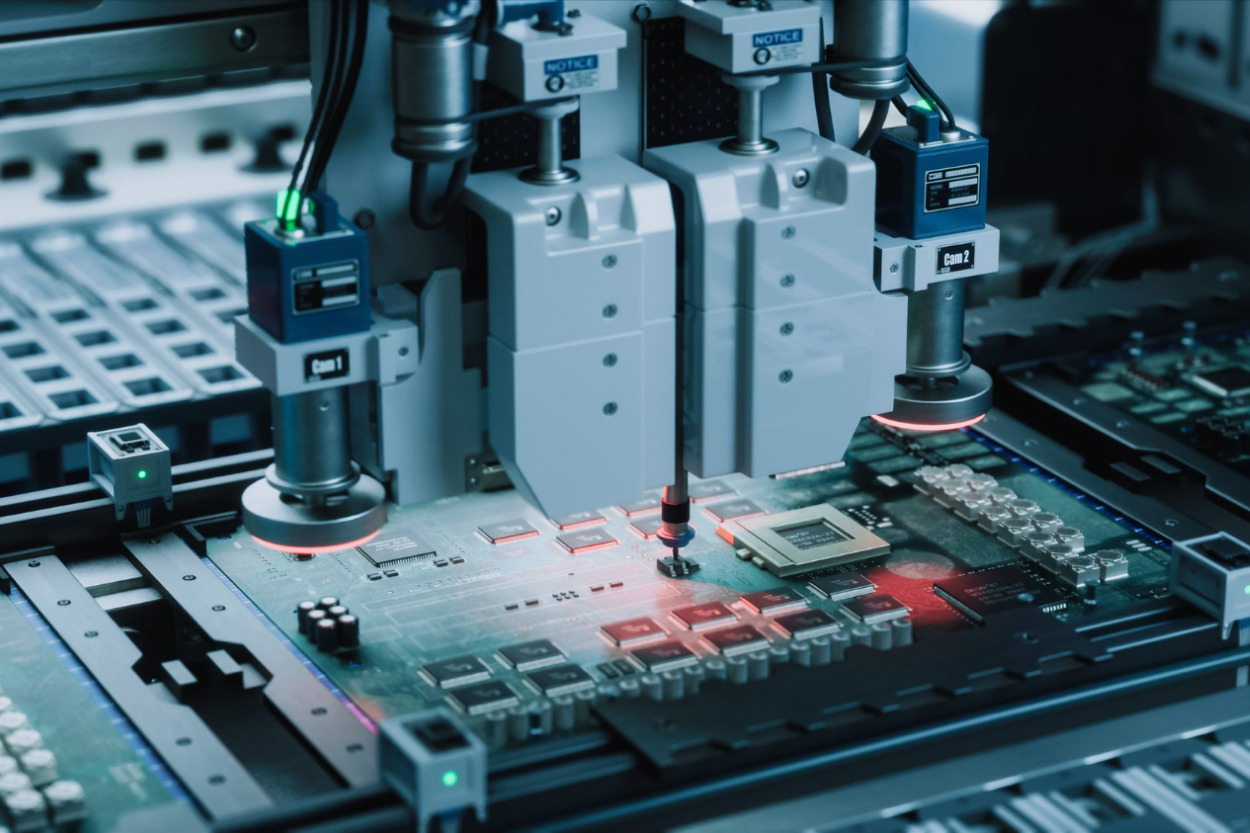
Consider a typical modernization scenario. The discontinuance notice covers one part: the motor driver IC on the main control board. The distributor already lists a successor from the same family — same package, same pinout, marked as the recommended replacement. On paper it is a two-week task for one hardware engineer.
It rarely stays that way. If the successor switches faster, the gate network changes and the board needs a new EMC pre-scan. If its current-sense output scales differently, the current-loop gains have to be retuned and re-verified across the payload range. If a test pad moves a few millimeters to make room for a snubber, the end-of-line fixture may stop contacting it. And if the enclosure was sized for the old losses, the thermal margin has to be checked again.
None of this requires anyone to be careless. It only requires sizing the job by the part instead of by the architecture around it.
Teams typically assume: replacing an obsolete component is a sourcing and layout task — find a drop-in successor, update the BOM, respin the board if needed.
In reality: in a mechatronic product, every component sits inside mechanical, electrical, thermal, firmware, test, and compliance dependencies at the same time. The size of a change is set by how many of those dependencies it crosses, not by the size of the part. That is why modernization starts by defining the architectural scope of the change — and only then choosing between replacement, partial redesign, and full redesign.
Quick Overview
Problem: A product that still sells has to change — an EOL notice, a rising BOM, a production bottleneck, or a new requirement — and the team has to decide how much of the design to reopen.
Common triggers: End-of-life and last-time-buy notices, BOM cost growth, low yield or slow production tests, performance ceilings, new interfaces, and new regulatory requirements.
Where it appears: Industrial automation equipment, drive units and actuators, dosing and packaging machinery, medical automation, automotive and off-road mechatronic units, and motion-based consumer products.
Engineering focus: A cross-discipline change-impact map, a written compatibility contract, an honest re-verification scope, and a production transfer plan — all before committing to a path.
Why Mechatronic Products Reach the Modernization Decision
There is rarely a single reason. Usually one trigger arrives and exposes several others that were already there.
End-of-life components. A supplier issues a product discontinuance notice. Semiconductor suppliers commonly provide a defined last-order and final-shipment window after such a notice; JEDEC J-STD-048A covers product discontinuance notification practices, but the actual window varies by supplier, and some parts disappear faster than planned. A last-time buy can bridge the gap. It does not close it, and it ties up cash in inventory sized to a forecast that may be wrong in either direction.
Rising BOM cost. A part that was reasonably priced at design-in moves to allocation pricing, or a single-source component loses its only competitor. Sometimes the problem is structural: the product is built around a discrete circuit that one newer integrated device now covers.
Production and test problems. Low first-pass yield, manual adjustment steps, a calibration routine only one technician fully understands, or an assembly sequence that a current EMS partner flags in DFM review. These are often the real cost of an old design, and they never show up on the BOM. The cost of finding them late is covered in DFM and test strategy mistakes during scaling.
Performance ceiling. The mechanism could deliver more — higher speed, tighter positioning, a longer duty cycle — but the controller, the sensor resolution, or the power stage cannot.
New interfaces and requirements. Customers ask for industrial Ethernet instead of a legacy fieldbus, for remote diagnostics, or for firmware updates in the field. Regulation moves as well. In the EU, the Machinery Regulation (EU) 2023/1230 applies from 20 January 2027: machinery placed on the market after that date is assessed under it, and it now defines substantial modification explicitly. The Cyber Resilience Act reporting obligations for products with digital elements have applied since 11 September 2026, with most other obligations following on 11 December 2027. Neither is a reason to redesign on its own, but both change what a modernized product has to document.
The trigger matters because it sets the constraint. An EOL-driven project is time-boxed by the last-time-buy window. A cost-driven project is bounded by payback. A requirement-driven project is bounded by what customers will accept as compatible. When a project mixes them without saying which one leads, the scope drifts.
One boundary is worth stating early. If the product is failing in the field and the root cause is still unclear, that is a diagnosis problem first — see how to isolate mechatronic failures across mechanics, electronics, and firmware. A modernization decision is only as good as the understanding of how the current product actually behaves.
What One Component Change Actually Touches
Follow a single replacement through a typical motion product:
discontinued part → footprint and pinout → power and thermal budget → EMC behavior → firmware drivers and timing → control-loop tuning → mechanical fit and enclosure → production test and fixtures → compliance evidence and documentation
Each arrow is a place where a “compatible” part can stop being compatible. A few patterns come up again and again.
A power MOSFET successor. Same package, lower Rds(on), different gate charge and switching speed. Conduction losses fall, but faster edges raise dv/dt, which can shift conducted and radiated emissions. The gate drive network may need to change, and the EMC evidence behind the product’s declaration of conformity has to be reassessed rather than assumed.
A capacitor with lower ESR. Replacing an aluminum electrolytic with a polymer part looks like an upgrade. On a regulator whose compensation relied on the output capacitor’s ESR, it can reduce phase margin and push the loop toward instability.
An encoder whose successor changes the interface. The flange and shaft match, but the successor offers BiSS C rather than the SSI variant the drive firmware reads — or it keeps the protocol and changes the resolution. Either way, the change reaches the drive’s interface logic, the cable and connector, and every parameter that scales position.
A motor from a different vendor. Similar torque and speed ratings, different rotor inertia and torque constant. The current and velocity loops need retuning, the load-to-motor inertia ratio moves, and thermal behavior at the real duty cycle has to be checked again.
An MCU replacement. New peripherals, different ADC sampling behavior, a different approach to non-volatile data, a new toolchain, and often a new programming step at end of line. Firmware that depended on the exact timing of the old core does not carry over unchanged.
The visible change is local. Its consequences are not. So the first engineering deliverable of a modernization project is not a part number — it is a change-impact map showing which disciplines, boards, and interfaces each candidate change reaches. That map is what makes the difference between the three paths concrete. It is also why modernization of mechatronic products works best when mechanics, electronics, and firmware are scoped by one team rather than three sequential ones.

Audit the Existing Product Before Choosing a Path
A modernization audit is not a documentation review for its own sake. Its job is to find every dependency a change could hit, and every unknown that could turn a small change into a large one.
| Audit area | What to check | Red flag that widens scope |
|---|---|---|
| Architecture | Block diagram, partitioning between boards, which functions depend on which parts | No current block diagram; functions split across boards in ways nobody can explain |
| BOM | Lifecycle status per line (active, NRND, LTB, EOL, obsolete), single-source parts, approved alternates | Several NRND or LTB parts on the same board; no qualified alternates |
| Mechanics | CAD matching the production revision, tolerance stack-ups, mounting and connector interfaces, tooling ownership | CAD does not match what is built; mold ownership unclear |
| Electronics | Editable schematic and layout sources, derating margins, known errata workarounds | Only Gerbers and PDFs survive; margins already thin |
| Firmware | Source availability, a buildable toolchain, version history, calibration data handling | Binary-only images; compiler licenses expired; builds that work on one machine only |
| Documentation | Requirements, test reports, compliance files, field-failure history | No test evidence for the current revision |
| Production tests | ICT and functional test coverage, fixtures, calibration steps, the origin of each test limit | Limits nobody can justify; fixtures tied to current board geometry |
| Dependencies | Host systems, protocols, spare-part interchangeability, customer integrations | Customers relying on undocumented behavior: timing, register values, error codes |
Missing information is a finding, not a blocker. The audit should end with two artifacts: a dependency map, and a list of unknowns with a plan to close each one — reverse engineering, behavior capture, or a targeted test. On the component side, the practical discipline of tracking BOM lifecycle status and approved alternates feeds directly into this step; IEC 62402:2019 describes the wider obsolescence management process for organizations that want to formalize it.
Three Modernization Paths
Path 1: Replace a Component or Critical Subsystem
What it is: a form-fit-function replacement where one exists; otherwise, a contained subsystem swap — a new drive board behind the same connector, a new sensor module on the same mount.
When it fits: the change-impact map stays inside one or two disciplines, the interfaces at the boundary can be held, and the product still has meaningful life ahead of it.
What it keeps: everything outside the boundary — enclosure, mechanism, host interface, and most of the firmware.
What to watch: “drop-in” parts that are only pin-compatible. Pin compatibility is not functional equivalence. Qualify the replacement against the product’s actual operating envelope — load, temperature, duty cycle, supply transients — not against the first page of the datasheet.
Path 2: Partial Redesign That Keeps Proven Parts
What it is: reopening one layer — most often control electronics and firmware — while freezing the mechanics, the enclosure, and the external interfaces. Sometimes it runs the other way: new mechanics around proven electronics.
When it fits: several obsolescence or cost problems cluster in one area, the mechanism and enclosure are proven in the field and expensive to requalify, and customers depend on the existing interfaces.
What it keeps: the parts with the most field evidence and the highest requalification cost.
What to watch: the boundary. A partial redesign works only if the frozen interfaces are written down — connector pinouts, mounting, protocol, timing, and behavior on errors. An undocumented boundary is where partial redesigns quietly turn into full ones. Designs built on a modular architecture that allows component substitution make this path much cheaper the next time around.
Path 3: Full Redesign
What it is: a new architecture that reuses requirements, field data, and test methods rather than hardware.
When it fits: obsolescence is spread across the design; the architecture blocks the new requirements, such as a new industrial interface or diagnostics; the product’s remaining life justifies the investment; or the change-impact map shows that the “partial” path would reopen almost every discipline anyway.
What it keeps: requirements, field-failure history, test methods, and whichever customer-facing interfaces must remain compatible.
What to watch: a full redesign is not automatically cleaner or cheaper. The redesigned architecture no longer has the same body of field evidence as the existing product, and it carries full verification, pre-compliance, and production transfer effort. For a redesigned architecture, pre-prototype CAE can reduce motion, thermal, structural, and control risks before hardware is committed. A full redesign should be justified by what the new architecture enables, not by frustration with the old one.
| Criterion | Replace | Partial redesign | Full redesign |
|---|---|---|---|
| Typical trigger | Single EOL or cost item | Problems clustered in one layer | Obsolescence spread across the design; new architecture needed |
| What stays frozen | Everything outside the part or subsystem boundary | Mechanics, enclosure, and interfaces (or the reverse) | Requirements and the interfaces customers depend on |
| Re-verification scope | Targeted delta verification | Layer-level verification plus system integration | Full V&V, pre-compliance, production transfer |
| Production impact | Fixture and programming updates | New boards and firmware into an existing line | New product introduction |
| Main risk | Hidden coupling behind a “drop-in” | A frozen boundary nobody wrote down | Losing field-proven behavior |

Replacing a Discontinued MCU Without Changing What the Equipment Sees
A manufacturer of sensor technology for industrial automation found that the NXP microcontroller in one of its distance sensors — part of production equipment in the field — had been discontinued. The goal was not a new sensor. It was the same sensor on a new MCU, with no change visible to the equipment it served.
Promwad tested candidate MCUs and selected the NXP MC9S08SH8, then migrated the firmware from Assembly to C. The compatibility contract was concrete: the same number of pulses, signal period, and duty cycle, and every existing detection mode — pump in, pump out, object, background, and proximity. In this project, the C implementation required more memory than the original hand-written Assembly, so the build was arranged to use a flash region the old firmware had left empty. The program kept a super-loop structure with a fixed cycle time, so timing stayed predictable.
The harder problem was information. Schematics and descriptions of the customer’s equipment were not available. Instead of guessing, the team recorded and analyzed the data exchange between the systems in Python to reconstruct how they interacted, then built a sensor simulator to validate the protocol before integration. The sensor stayed in production without downtime.
Full engineering write-up: → Migrating sensor firmware from Assembly to C on a replacement MCU
The same scoping logic shows up in other Promwad modernization work:
- Replace, with software rework: when components of a truck 360-degree camera system were discontinued, Promwad replaced them and reworked the software on a Lattice CrossLink-NX FPGA and an NXP S32K148 MCU, while the client kept ownership of the hardware design. → 360-degree camera system update
- New capability, no board revision: analog PAL/NTSC output was added to a new-generation vision platform by porting and validating a Linux driver, so the existing board stayed exactly as it was. → Analog video output without a board redesign
- Partial redesign of a product in production: a portable broadcast device received new HDMI and USB interfaces, four LTE modems instead of two, a touch screen, a LiFePO4 battery, and OTA updates as a next-generation version. → Improving portable live streaming equipment
Decision Criteria That Should Drive the Choice
Six criteria do most of the work. None of them is new; the value is in answering all six before the path is chosen.
Remaining product life. How many more years will this product ship and be supported? A short tail favors a last-time buy plus a targeted replacement. A long tail favors fixing the architecture once instead of paying for the same kind of change every few years.
Scale of the linked changes. Read it from the change-impact map: how many disciplines, boards, and interfaces does each option reopen? A “replacement” that reopens four disciplines is a partial redesign with a misleading name — and it should be budgeted like one.
Component availability. Not only for the failing part, but for everything that will stay. Replacing one EOL part while three NRND parts remain on the same board buys very little time.
Compatibility constraints. What must stay identical for customers, host systems, spare-part interchangeability, and the installed base? The tighter this contract, the more a full redesign has to reproduce, and the more expensive it becomes.
Cost of re-verification. Functional tests, EMC and safety pre-compliance, recalibration, updates to risk analysis, and customer requalification. In mechatronic products this can outweigh the design work itself, and it grows with the scale of the change.
Production risk. New fixtures, new programming steps, possible EMS changes, first-article inspection — and what happens to units already in the field and spares already in stock.
The criteria rarely point the same way. When they conflict, the constraint that started the project decides: the time window for an EOL-driven change, payback for a cost-driven one, and compatibility for a product with a large installed base.
How to Keep What Works: Mechanics, Enclosure, Interfaces, and Software
Mechanics and enclosure usually carry the most tooling cost and the most field evidence: injection molds, seals, test results for IP ratings under IEC 60529, vibration and climatic test history. Keeping them means the new electronics must fit the old envelope — board outline, mounting points, connector positions, and heat path. The last one is the one teams forget. An enclosure sized for the old power stage has to be re-checked against the new losses; see steady-state thermal limits under continuous load. Where mechanics do change, mechanical design should start from the frozen interfaces, not from a blank model.
External interfaces are frozen at the boundary: connectors, pinouts, protocols, register maps, timing, and error behavior. In Promwad’s electric truck retrofit, the engine, gearbox, and exhaust were removed, but braking, safety assistants, camera, and radar kept working because the team emulated the signals of the removed sensors over custom CAN and LIN drivers and an auxiliary board. The surrounding system never saw the change.
Software assets need to be separated into two groups. The valuable ones — control algorithms, calibration data and procedures, protocol stacks, test scripts — are worth carrying forward. The hardware-bound ones — drivers, startup code, timing loops — usually are not. Introducing a hardware abstraction layer during the migration is what makes the next EOL event cheaper; MCU firmware porting and migration is often where that layer gets built. For controllers where the move is larger than one chip, the staged migration from legacy MCUs to multicore platforms follows the same principle.
Production assets include test sequences, limits, and fixtures. Keep test points in place when a board is re-laid out, and reuse functional test sequences wherever the geometry allows. In-production testing is one of the cheapest things to preserve and one of the most expensive to rebuild under schedule pressure.
Backward Compatibility Without Carrying Old Limits Forward
Backward compatibility fails when it is treated as a feeling (“it should behave the same”) instead of a written contract. For a mechatronic product, the contract has six layers:
- Mechanical: mounting, envelope, connector positions, and sealing that affects the IP rating.
- Electrical: supply range, I/O levels, inrush current, and grounding scheme.
- Protocol: messages, register maps, timing, and error codes.
- Behavioral: motion profiles, response times, start-up behavior, and what the host sees during faults and power-up.
- Parameters and data: configuration files, calibration values, and stored logs.
- Service: spare-part interchangeability, a firmware update path for units already in the field, and hardware revision identification so firmware knows which board it is running on.
Verification is comparative. Run old and new units through the same test sequence on the same fixture, record the outputs, and compare them against defined tolerances. Keep a few reference units from current production for exactly this purpose. Where documentation is missing, capture the behavior from the running system — the same approach the MCU migration above used when the equipment schematics were unavailable. For products that cannot stop running during the transition, a staged migration that keeps production running lets the new controller observe before it takes control.
The opposite risk is quieter: carrying the old product’s limits into the new architecture. Many constraints in a legacy design exist only because of the parts it was built with:
- Firmware delays and workarounds for silicon errata of the old MCU.
- Reduced update rates or baud rates set by the old processor’s throughput.
- Derating and oversized heatsinks set by the old power stage losses.
- Scaling factors and fixed-point formats tied to the old ADC resolution.
- Manual calibration steps that compensated for component tolerances the new parts may not have.
The rule is to keep compatibility at the boundary, not in the core. If a host expects an old protocol quirk, reproduce it in the interface layer and design the internal architecture for the new parts. Document each preserved quirk with the reason it exists, so it can be removed when the last legacy host is retired.
Real Trade-Offs to Expect
- Keeping the enclosure saves tooling and requalification, but it constrains board outline, connector placement, and the heat path. The new electronics inherits the old thermal envelope.
- A last-time buy buys time, but it ties up capital, needs controlled storage for moisture-sensitive parts, and depends on a forecast that can be wrong both ways.
- Strict backward compatibility protects the installed base, but it freezes protocol and timing decisions the new platform could make better.
- An adapter or interposer board can avoid a main-board respin, but it adds a connector, height, and a new failure point. It is a bridge, not a destination.
- Moving firmware to a higher-level language or an RTOS improves maintainability, but it can increase memory needs, and the rewritten code does not inherit the field history of the original.
- A full redesign opens the door to new capabilities, but the new design has less field history behind it and carries full verification and pre-compliance effort.
You May Be Facing This Decision If
- You received a discontinuance or last-time-buy notice for a part on a motion, power, or sensing path.
- The recommended replacement is pin-compatible but has not been characterized in your operating envelope.
- More than one part on the same board is already NRND or LTB.
- Production yield, calibration time, or test coverage has become a bigger problem than component cost.
- Customers need a new interface, diagnostics, or field updates that the current controller cannot support.
- The firmware builds on one old machine only, or part of the source is missing.
- Nobody can say with confidence which behaviors of the current product customers actually depend on.
How Promwad Helps
Modernization work at Promwad starts with the existing documentation and test data and ends with the smallest change set that solves the problem. Typical engagements:
- A modernization audit across architecture, BOM lifecycle, mechanics, electronics, firmware, and production tests, with a change-impact map for each option.
- Component and subsystem replacement, including MCU migration and firmware porting behind unchanged interfaces.
- Partial redesign of control electronics and PCB layout inside a frozen mechanical and protocol boundary.
- Drive and motor control modernization where motors, encoders, or power stages change.
- Full redesign through prototype, verification, and production transfer as part of mechatronics design services.
- Pre-compliance testing and documentation support; the manufacturer remains responsible for the applicable conformity-assessment and certification process.
Planning to modernize a product that is already in production?
Explore Mechatronics Design Services →
FAQ
When is replacing a single EOL component enough?
Is modernization always cheaper than a full redesign?
How do we verify backward compatibility?
Can we keep the existing enclosure and mechanics?
Does a modernized product need to be retested for compliance?
What information do you need to start?
Related Promwad Expertise
- Migrating Firmware from Assembly to C: replacing a discontinued NXP MCU in an industrial distance sensor while keeping pulse count, signal period, duty cycle, and detection modes unchanged.
- 360-Degree Camera System Development for Trucks: replacing discontinued components and reworking software on Lattice CrossLink-NX and NXP S32K148.
- Analog Video Output Without a Board Redesign: a new capability delivered at the driver layer while the existing board stayed unchanged.
- Electric Truck Retrofit for Utility Vehicles: preserving the vehicle’s original systems by emulating signals from removed sensors.
- Mechatronics Design Services: mechanics, electronics, and firmware under one team, including modernization of existing systems.
- Why Mechatronic Products Fail at Discipline Interfaces: the diagnostic companion to this article, for products that are already failing.
Tell Us About the Product You Need to Modernize
Share what the product does, what triggered the change — an EOL notice, a cost target, a production problem, or a new requirement — and which parts of the design you want to keep. We will help define the smallest change set and the verification it needs.