


Simulation Before a Mechatronic Prototype: What CAE Can Evaluate and What Hardware Must Confirm

A mechatronic team is close to cutting metal for the first prototype of a positioning stage. The kinematics are drawn, the motor is chosen against nominal torque, the enclosure is on order. On paper, everything closes.
Then someone asks about the acceleration profile the machine will actually run, not the top-speed spec. The motor was sized for steady-state cruise. Under the transient the machine will do many times an hour, the current draw pushes the drive into its thermal derating band within minutes. On the prototype, this often surfaces as intermittent step loss and gets chased through the encoder, the firmware, and the bearings before it is traced back to the sizing decision.
Pre-prototype simulation is scoped to catch this class of issue. It does not replace the prototype. It narrows the design space, exposes the assumptions that need testing on hardware, and defines what the prototype is there to confirm.
Teams typically assume: if the datasheet numbers match and the CAD model closes, the first prototype will validate the concept.
In reality: the first prototype is where hardware confirms or refutes an architecture. If the architecture was chosen without evaluating the duty cycle, the transients, the thermal budget, and the control dynamics together, the prototype often becomes a discovery activity rather than a confirmation activity — the most expensive way to surface a wrong assumption.
Quick Overview
Problem: A mechatronic concept looks correct in datasheets and CAD, then fails on the first prototype in ways that could have been evaluated earlier — undersized actuators, unstable control loops, thermal ceilings hit under duty cycle, structural modes near operating speed.
Common causes: Steady-state sizing without transient analysis, single-point calculations without a stated uncertainty range, no consistent comparison between architectural options, and treating the prototype as the first opportunity to evaluate motion, thermal, and control behavior together.
Where it appears: Multi-axis motion stages, robotic arms and delta pickers, precision drives, thermal-management assemblies, actuator modules, and any product where mechanics, power electronics, and control firmware have to hold a spec together.
Engineering focus: Requirements written against the real duty cycle, models scoped to answer the questions the prototype cannot answer cheaply, sensitivity analysis against realistic tolerances, and a physical PoC scoped to the assumptions the model cannot close on its own.
What CAE Can Evaluate Before Hardware
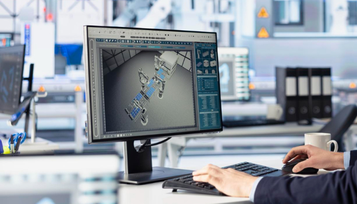
Pre-prototype simulation turns requirements into pass/fail engineering questions the model can answer. Practically, it covers:
- Kinematics and reachable envelope. Whether the mechanism can reach every point in the workspace, at every orientation the task requires, without singularity or collision.
- Actuator and drive sizing under the real duty cycle. Peak torque, RMS torque, back-EMF, current under acceleration, and thermal derating over the full motion profile — not only at the top-speed operating point. A motor that clears its nameplate spec at cruise can still saturate on a start-up transient run frequently by the application.
- Energy, power, and cooling budgets over the mission. Battery capacity is sized against the integral of power over the duty cycle. The DC bus, drive, and PSU are sized against peak, transient, and continuous current, together with regeneration if applicable. The cooling path is sized against dissipated losses and required junction and case temperatures. Each of these is a separate calculation on the same mission profile.
- Thermal behavior in steady state and under transient load. Junction temperatures, hot-spot migration, time to thermal equilibrium, and derating curves. CFD-based thermal analysis helps predict components at risk of exceeding their limits before the first board is submitted, and does the same for enclosures. Promwad covers this discipline as part of SI, PI, and thermal analysis.
- Structural loads, stiffness, and modal behavior. FEA helps evaluate whether the frame or gantry deflects under load in a way that affects accuracy, and whether any natural frequency sits close to the operating speed or its harmonics. See vibration and shock simulation in hardware development for how FEA fits into a normal design flow.
- Control concept and closed-loop dynamics. Whether the chosen PI or cascaded loop structure can reach the required bandwidth, phase margin, and disturbance rejection given the inertia, sensor latency, and actuator dynamics. If the plant is fundamentally too compliant or too under-damped for the required bandwidth, firmware tuning alone will not close it later.
- Flow behavior for cooling and fluidic systems. Air or liquid path, pressure drop, dead zones, fan operating point. CFD used the way Promwad describes it in air-cooling design — to evaluate the enclosure virtually before machining it.
Each of these produces an engineering artifact — a curve, a mode shape, a temperature map — that either fits inside a requirement or does not, within a stated uncertainty range.
Comparing Architectures Before Commitment
A mechatronic architecture is a choice between plausible options: gearbox versus direct drive, belt versus lead screw, brushed DC versus BLDC versus PMSM, embedded MCU versus DSP for the control loop, air cooling versus liquid, one large actuator versus two synchronized. Every fork changes cost, weight, footprint, and control behavior at the same time.
The value of pre-prototype simulation for this decision is comparison under identical assumptions. When the same model is exercised against each candidate architecture with the same duty cycle, the same payload, and the same uncertainty range on parameters, the meaningful quantity is the difference between options — evaluated consistently — rather than the absolute number for any single one.
Comparison also surfaces the assumptions that separate the options. A direct-drive architecture puts the full load on the motor and the bearing. A gearbox lowers the reflected inertia and required peak torque, but adds backlash, efficiency loss, and audible ripple. Which one wins depends on whether the application tolerates backlash and where the noise floor sits. The simulation does not decide; the engineer decides. What simulation offers is that the trade is visible before hardware is committed.
Sensitivity Analysis and Corner Cases
Motors ship with tolerance bands on torque constant and resistance. Bearings ship with friction that varies with temperature, lubrication age, and load. Belts stretch. Encoders have quantization and, past the datasheet, real noise. Ambient temperature and line voltage vary. A design that only closes at the nominal center of every distribution may not hold across production.
Sensitivity analysis exercises the model at the edges of these distributions. Vary the motor constant across its tolerance band. Push the ambient to the worst case of the environmental spec. Increase friction by an amount consistent with lubrication drift or manufacturing variation. Add the sensor noise the datasheet promises but the demo did not have. The result is an envelope of behavior around a stated uncertainty range, rather than a single number.
This is where the corners of the operating region get evaluated. A steady-state cruise at room temperature is easy. Cold start with a fully loaded axis, a marginal-batch motor, and reduced line voltage is the corner that most often causes field issues. If the corner still closes in simulation, the design has computed margin. If it does not, the sizing needs another pass — before the prototype is fabricated.
What Simulation Cannot Confirm on Its Own
A model is only as good as the physics it captures and the parameters it is fed. Several categories of behavior in a mechatronic product are confirmed on hardware rather than by simulation alone.
- Real friction, not modeled friction. Coulomb friction, viscous friction, Stribeck behavior, and the way seals and bearings behave near zero velocity resist clean parametric modeling. A simulation with a nominal friction coefficient may predict smoother motion than the physical device delivers.
- Backlash and lost motion. Gears have backlash. Belts have wind-up. Couplings have hysteresis. Values are batch-dependent and often measured, not specified. A control loop tuned only against a zero-backlash model may produce reversal error, limit cycles, or oscillation on the physical machine.
- Component-to-component dispersion. Two motors from the same production lot do not have identical torque constants. Two encoders do not have identical quantization noise. Simulation works with distributions; the prototype delivers actual devices, and model correlation is what pulls the two closer together.
- Sensor noise and offset. Datasheet noise is a specification, not a promise. Real noise, drift, temperature sensitivity, and cross-axis coupling fully surface only when the sensor is mounted where it will operate. This is especially true for MEMS gyros, current sensors near switching converters, and hall-effect encoders near ferrous frames.
- EMI and EMC. Radiated and conducted emissions can be simulated in narrow senses at PCB and harness level, but the full behavior of a mechatronic system in its intended environment is measured. That is why EMI/EMC-aware schematic design matters as a discipline, and why EMC pre-compliance is a physical activity.
- Assembly and tolerance stack-up. A GD&T stack-up can be computed. Whether the actual parts, from the actual suppliers, in the actual assembly sequence, land inside that stack-up is a hardware measurement.
- Wear, drift, and long-term behavior. Simulation predicts nominal life; long-duration soak, thermal cycling, and vibration endurance are physical tests carried by prototypes and pre-compliance units.
- Environmental exposure and IP compliance. The tests defined in IEC 60529 (ingress protection) and IEC 60068 (climatic and mechanical testing) require physical exposure of the actual product. A physical test result can demonstrate conformance to a specified IP class or environmental requirement, but full certification depends on the broader compliance chain — accredited labs, documentation, and, where applicable, third-party review. Simulation informs the enclosure design; it does not substitute for that chain.

The Sequence That Reduces Prototype Iterations
Every mechatronic program benefits from the same broad order. The steps are not exotic; the discipline is running them in sequence rather than compressing them.
- Requirements. Written against the real duty cycle, the real environment, and the real corner cases — not marketing top-line specs. Every downstream step is only as good as this input.
- Model. A representation of the mechanism, the actuator and drive, the sensors, the control loop, and the environment, connected in a single simulation the team can exercise. Fidelity should match the questions the model has to answer, and the model should be explicit about what it includes and what it does not.
- Simulation. Against the requirements. Every requirement becomes a pass/fail question, and every result is an engineering artifact with a stated uncertainty.
- Sensitivity analysis. The same simulation, exercised across the tolerance and environment envelope. This is where the model earns the right to claim the design has computed margin.
- Physical proof of concept. A bare mechanism, often on 3D-printed parts, that confirms the physical behavior the model cannot close on its own: friction, backlash, real sensor noise, and the raw feel of the motion. Promwad describes this step explicitly on the mechatronics design services page — CAE sits between feasibility and PoC, and a physical PoC follows.
- Model correlation. Measurements from the PoC feed back into the model so the model represents the hardware within a stated error bound. Only a correlated model can be used to predict what a redesign will do, rather than what the engineer expects it to do.
When simulation is applied to an existing product, the redesign scope has to be defined before the model is used to evaluate the next revision. Deciding what to keep, replace, or redesign in an existing product establishes which proven parts remain fixed and which mechanical, electronic, firmware, or control dependencies need to be reopened. - Prototype. At this point, the prototype is a design confirmation activity rather than a discovery activity. It carries what the model and the PoC together said it would carry.
When the industry talks about compressing prototype-to-production cycles, this is the sequence being described. See rapid prototyping and manufacturing of complex electronics for the broader lifecycle discussion.

Model Correlation and the Digital Twin Boundary
Model correlation is a prerequisite for calling a model a digital twin, but it is not the whole definition. As formalized in the NIST core conceptual models for digital twins, a digital twin requires a live, bidirectional connection with a specific physical instance so that the model and the hardware stay synchronized during operation. Pre-prototype simulation has no physical counterpart yet. A correlated model after PoC has the parameters right but not yet the live coupling.
The general pattern of model-based iteration continuing after deployment is discussed in digital twins for robotics. Before deployment, the useful phrase is "correlated simulation model" rather than "digital twin" — the latter is earned once the sync is in place.
An Illustrative Example
A rotary actuator is specified against a peak torque and a top speed. The catalog motor clears both at nominal ambient. The team commits to the mechanical envelope, orders the drive, and moves on.
The real duty cycle is a rapid index-and-hold: the actuator accelerates, decelerates hard, and holds position under load, then repeats. Exercised end-to-end against the full cycle rather than at a single operating point, the RMS current can sit above the drive's continuous rating, and the motor's thermal time constant is short enough that it approaches its thermal limit within a few minutes of running. On the bench at low duty, this behavior is invisible. At production duty, the drive derates.
The response is one of three cheap decisions on paper: a motor one frame size larger, a gearbox ratio that lowers the reflected inertia, or a duty cycle the mechanical team agrees is unrealistic and can be relaxed. Each becomes expensive once a prototype exists. The same pattern recurs for structural modes near an operating frequency, control loops whose required bandwidth exceeds what the mechanical compliance allows, and thermal budgets that close in CAD and fail inside the enclosure.
Illustrative example based on a common failure pattern; not a specific Promwad project.
You May Be Facing This If
- The first prototype has to answer questions about motor sizing, thermal behavior, and control stability all at the same time.
- Requirements exist as top-line specs, but the full duty cycle the machine will actually run has not been written down.
- An architecture has been chosen (direct drive, belt, gearbox, cooling scheme) without a documented comparison against the alternatives under the same assumptions.
- Sensitivity to component tolerance and environment has not been analyzed, so the design "should work" at nominal without a stated margin.
- The mechanical team, the electronics team, and the firmware team hold separate models, with no shared simulation to reconcile them.
How Promwad Helps
Promwad delivers mechatronic development as one engineering team across mechanical, electronics, embedded software, and control. The same team that runs the pre-prototype simulation owns the boards, the firmware, and the mechanics — so results feed forward without translation loss.
- CAE feasibility and concept evaluation as a standalone project scope or as part of a full mechatronic engagement: motion, thermal, vibration, structural, and flow analysis carried through to pass/fail results against your requirements. Listed on the Mechatronics Design Services page.
- Electronics-side simulation. Signal integrity, power integrity, and thermal analysis for high-speed and power boards, reducing board spins before tape-out.
- Physical PoC and model correlation. After simulation, a PoC on 3D-printed parts confirms motion behavior physically, and its measurements feed back into the model. That is when the simulation becomes a design tool for the next revision instead of an initial estimate.
Planning a mechatronic prototype?
FAQ
Does simulation replace the first prototype?
What can be evaluated before the first hardware, and what still needs the PoC?
Is a "digital twin" the same thing as pre-prototype simulation?
Related Promwad Expertise
- Mechatronics Design Services: end-to-end mechatronic development with mechanical, electronics, firmware, and control engineering under one team, backed by thermal, vibration, and flow simulation.
- SI, PI, and Thermal Analysis: pre-layout and pre-tape-out simulation for high-speed and power electronics, integrated with the mechatronic simulation flow.
- Motor Control Engineering: BLDC, PMSM, and stepper drive engineering, with control-loop implementation on the same team that runs the simulation.
- Studio-Grade Direct-Drive Turntable: full-cycle mechatronic design where a diagnostic phase separated mechanical, electronic, and control causes before development committed.
- Delta Robot Design for Conveyors: three-axis motion architecture with cascaded position, velocity, and current loops on EtherCAT.
Tell Us About Your Mechatronic Project
Share the mechanism, the duty cycle it has to hold, and where you suspect the design carries the most risk before the first prototype. We will define the pre-prototype simulation scope that answers those risks and the physical PoC that closes the rest.