



PCB Signal Integrity, Power Integrity & Thermal Analysis
Some problems stay hidden until it's expensive to fix them: signal, power and thermal issues can surface on the first prototype or in the field, when every fix means another board revision, a delayed launch and a higher development budget.
Promwad runs SI, PI, thermal and EMC analysis on your design at the schematic and layout stages, whether we designed the board or not. You get a report with concrete fixes, so decisions on layout, cooling and enclosure are made on data rather than on the next prototype.

What We Analyze
| Analysis | What we check | What it prevents |
| Signal integrity (IBIS-based) | Reflections, crosstalk, timing and impedance discontinuities, at schematic and layout stages | Unstable links, costly rework after prototyping |
| Power integrity | DC drop, decoupling and plane noise in high-current and highly integrated designs | Rail droop, random resets, faults that are hard to reproduce in the lab |
| Thermal simulation | Hot spots and gradients on the board; airflow, vent placement and heatsink area in the enclosure | Overheating in long-term use, warranty costs on the client site |
| EMC analysis of the layout | Current loops, return paths, shielding and filtering | Failed certification, extra test iterations |
| System-level simulation (SPICE, PLECS, Simulink) | Losses, ripple current and temperature rise in power stages under real load profiles | Over- or under-dimensioned power components and cooling |
| 3D modeling | Board model integrated with the enclosure, reused for thermal and SI/PI analysis | Late mechanical conflicts, slower enclosure design |
A Design Review for Any Board
You don't need to hand over the whole project. We analyze designs made by your team or by another vendor, as a standalone scope. It is the lowest-commitment way to work with Promwad, and often the fastest way to avoid a respin.
What we need from you: schematic and layout files (Altium, PADS, KiCad or ODB++), the part list or IBIS models, a power budget and, for thermal work, the enclosure model.

When to Run Each Analysis
The earlier an analysis runs, the cheaper the fix it points to.
| Design stage | Analysis | Why at this stage |
| Architecture | System-level power simulation, PI budget, thermal concept | Component count, cooling method and enclosure material are still open |
| Schematic | Pre-layout SI on critical interfaces, decoupling strategy | Topology and termination can change at no cost |
| Layout | Post-layout SI/PI, EMC review | Margins are confirmed before fabrication |
| Enclosure design | Thermal and airflow (CFD) simulation | Vents, heatsinks and materials are chosen on data |
| After a failed test | Targeted SI, PI, thermal or EMC analysis | The root cause is found before the next revision |
What You Receive

Want us to apply the fixes too? The same engineers handle PCB layout and high-speed PCB design, or can take on the full product scope through our hardware design services.
Simulation Case Studies
Power Inverter Sized by Simulation for a Tier-1 Supplier
Automotive · PLECS + Simulink · 16 kW electric machine
Pain. A leading European Tier-1 automotive supplier needed an inverter power stage for a 16 kW electric machine. Too few parallel components would overheat; too many would inflate cost and size.
Solution. We built PLECS models of the selected components and calculated heat dissipation under load profiles taken from the motor specification. A Simulink model of the liquid cooling system, including chamber surface area and coolant flow speed, gave the temperature rise of the power stage. We then ran every driving profile with different power modules and DC-link capacitor counts.
Result. The number of parallel components was optimized for the 16 kW load with safe over-temperature stress on the power modules. The DC-link capacitor count was set by both temperature and simulated ripple current.
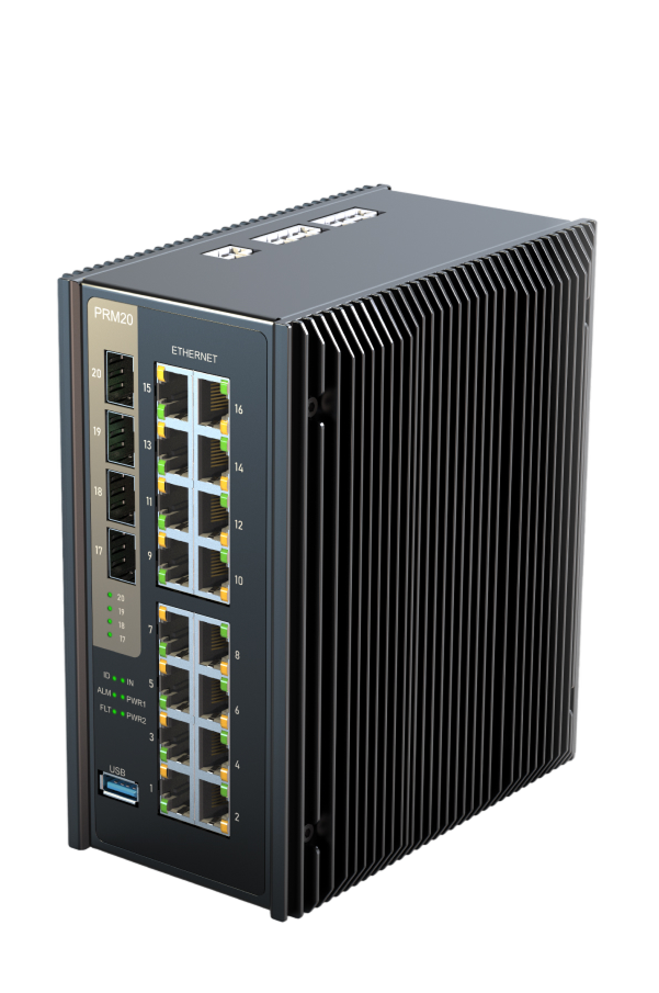
Passive Cooling for an Enterprise-Class Managed Switch
Telecom · Thermal and airflow simulation
Pain. An L2/L3 managed switch had to run with fully passive cooling. Any component that overheated would only show up after manufacturing started.
Solution. We ran a thermal simulation of the whole device to find hot components at the design stage. Fixes included moving components, changing the PCB and thermal pads, and airflow visualization confirmed the heat exchange at the radiators.
Result. A fanless switch that dissipates all its heat through two radiators on both sides of the device, with overheating risks closed before production.
Enclosure Choice Settled by Thermal Simulation
Consumer electronics · Thermal and flow simulation · Enclosure design
Pain. A European tech company with its own serial production needed an enclosure for an ARM-based smart player. Metal would move heat away from the board but cost more; plastic was cheaper, if it could keep the CPU cool.
Solution. Thermal simulation showed that heat did not need to be routed into the enclosure. We then compared passive cooling for four perforation options: average CPU temperature varied from 119.6 °C to 129.3 °C between them.
Result. The client chose a cheaper, more practical plastic enclosure with a standard radiator and a large perforation at the bottom, the option with the best cooling of the four.

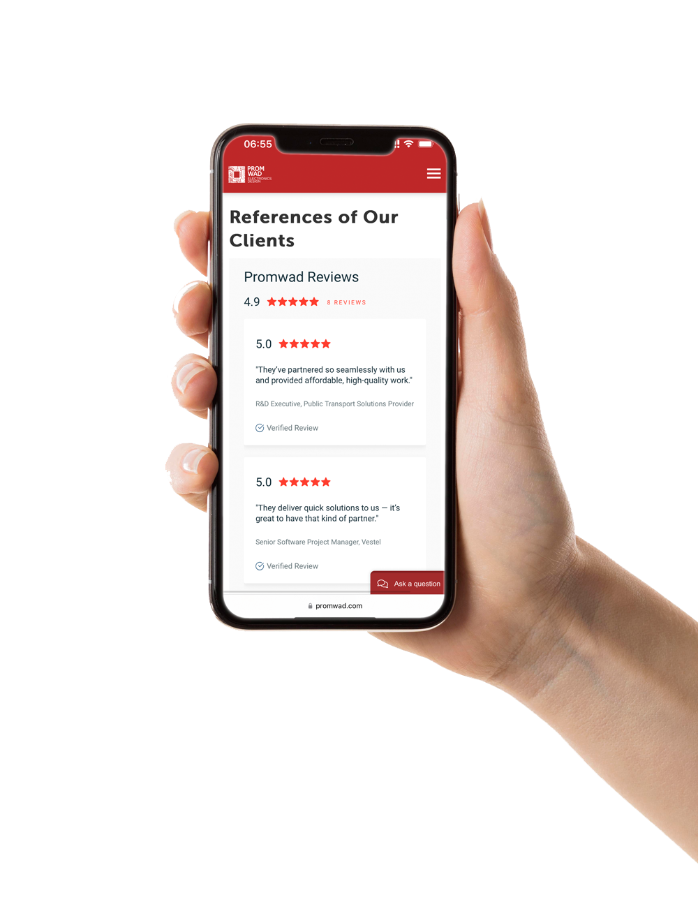
What Our Clients Say
“They offered a smart solution for our product. Small but effective changes in software and circuit design increased battery life over 3 times!”

“Promwad's team of highly motivated engineers and developers with diverse expertise helped us fill knowledge gaps and broaden our perspective. The partnership with Promwad has since become an indispensable asset to our product and development department.”
Find the Risks Before You Pay for Prototypes
Send us your schematic, layout or enclosure model and tell us what worries you. Our engineers will propose the analyses that matter for your design and a fixed scope for the review.
FAQ
What is SI/PI analysis, and when does my board need it?
Can you analyze a design made by another company?
Which simulation methods and tools do you use?
Can simulation replace prototype testing?
How long does a design review take?