


Why Deterministic Motion Loops Break When Physical AI Runs on the Same SoC
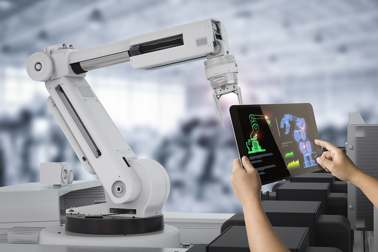
The demo worked. The VLA model picked the right object, the planner generated a smooth trajectory, and the arm reached the bin within tolerance.
Three weeks into pilot integration the story changed. The joint controller missed its 1 ms cycle every few seconds. End-effector overshoot grew from sub-millimetre to several millimetres. Twenty minutes into a sustained run the box temperature crossed 90 °C and the entire closed-loop response collapsed for thirty seconds at a time.
Nothing in the model had changed. Nothing in the control law had changed. The two had simply never been on the same SoC, at full load, at the same time.
This is the gap most physical AI projects hit and most demos hide. The neural stack — a vision-language-action model, a diffusion policy, or whatever sits at the high level — wants tens to hundreds of milliseconds of inference and a lot of memory bandwidth. The motion stack wants a hard, bounded response time measured in microseconds. Put both behind the same memory controller, the same thermal budget, and the same scheduler, and the question is no longer whether each works. The question is whether the system holds its loop when they run together.
Quick Overview
Problem: Perception and motion control validated separately on the bench miss closed-loop timing once they share the same SoC under production load.
Common failure points: VLA / diffusion-policy inference interleaved with the control task, LPDDR memory contention between NPU and CPU, ROS 2 DDS middleware jitter, thermal throttling on edge SoCs, and lifecycle bugs in fast/slow-loop synchronisation.
Where it appears: Service robots, mobile manipulators, AMRs, humanoid platforms, drones with onboard perception, and industrial cells where Jetson- or Qualcomm-class perception sits next to EtherCAT / CANopen joint control.
Engineering focus: Worst-case execution time (WCET) under real workload, fast/slow-loop partitioning across heterogeneous cores, memory-bandwidth budgeting, RTOS or PREEMPT_RT placement, and validation under sustained thermal load.
Wrong Assumption
The assumption that breaks first is the one teams rarely state out loud: if the AI model meets its inference time and the motion controller meets its cycle time, the integrated system meets its end-to-end behaviour. That is true on a clean bench. It is rarely true on a loaded edge SoC. Inference is not a fixed cost — it spikes with input distribution, it competes for the same LPDDR bandwidth the control task reads sensors over, and it pulls the package into thermal regions where the SoC quietly throttles. Deterministic motion is not just a control-law property; it is a property of every layer beneath the control law — the kernel, the middleware, the memory subsystem, and the thermal envelope. Validate them separately and you have validated nothing about how they behave together.
Why It Fails
Inference jitter colliding with the control cycle. A 1 kHz joint controller has a 1 ms budget per cycle. A VLA model takes 80–400 ms per forward pass on a Jetson Orin-class platform, a diffusion policy takes another 30–100 ms of denoising, and the planner runs somewhere between them. None of those fit inside the control budget — and that is fine, as long as the architecture separates them. When they share a Linux thread pool, an executor queue, or just a single memory controller, the spikes from upstream eat the headroom of the downstream task. The same pipeline-rather-than-model latency pattern that breaks vision systems breaks motion systems, only the consequences are mechanical instead of dropped frames.
OS scheduling and middleware overhead. Stock Linux schedules tasks for throughput; its preemption latency runs into the hundreds of microseconds and the worst case is unbounded. PREEMPT_RT brings the typical worst case down to roughly 50–100 µs, Xenomai/EVL pushes it under 20 µs, and a Cortex-M / R running an RTOS or bare-metal firmware sits below 1 µs. ROS 2 adds another layer: the DDS middleware (Fast DDS, Cyclone DDS) serialises every message, and a single-threaded executor sharing a callback queue with a high-rate sensor topic can stall a control callback by tens of milliseconds. Promwad's guide to RTOS and timing in advanced embedded systems walks through where each option fits.
Memory bandwidth and cache contention. On most edge SoCs the application cores, the GPU, the NPU and the ISP all reach the same LPDDR controller. A VLA forward pass can saturate that channel; once it does, an unrelated control task that needs to read a force sensor sees its memory access stall. The same effect appears at the cache level — a perception thread evicts lines used by the controller and the controller pays the miss the next cycle. This is the same family of effect documented in embedded AI hardware platform behaviour under sustained load and it shows up identically on the motion side.
Thermal throttling under sustained workload. A Jetson Orin or Qualcomm RB3 Gen 2 running a 100 TOPS-class inference workload spends real wattage. Once junction temperature crosses the SoC's threshold (typically 90–100 °C), the platform reduces clock and TOPS — and the inference time that was 80 ms at minute one becomes 130 ms at minute twenty. Closed-loop systems built against the cold number quietly miss the warm one.
Fast/slow-loop synchronisation. The standard architectural answer is to put motion on a real-time core and perception on the application core. That works, but only if the data handoff between them is engineered. The control loop must run on the freshest available perception result without waiting for the next one, and it must reject perception results that arrive with stale timestamps. The same partitioning question shows up in combining EtherCAT motion control with AI vision — the layering decisions made there are the same ones that decide whether a physical AI loop holds.
In production these arrive together. Inference jitter pushes a control deadline; the missed cycle delays a force-sensor read; the control loop's PI integrator winds up against stale feedback; ten minutes later thermal throttling stretches the inference further, and the system that passed the cold bench is mechanically unstable on the warm shop floor.
Hidden System Complexity
sensors (encoder / IMU / force / camera / LiDAR) → driver / DMA → state estimation (Kalman, sensor fusion) → perception (VLA / diffusion / detector) → planner → controller → joint command → fieldbus (EtherCAT / CANopen / CAN-FD) → drive → actuator → physical state
Once perception becomes part of that path, the timing problem expands beyond the conventional motion stack. Sensor acquisition, inference, planning and data handoff now consume time before the controller and fieldbus even act, while the actuator still has its own physical response. That makes industrial control-loop budgeting once perception is added an end-to-end exercise rather than a controller-cycle calculation.
The motion loop is not one stage in that path. It is the bounded window the whole path has to close inside, and any layer can quietly steal from that window. An encoder sample that takes 50 µs longer than expected, a DDS callback that fires 800 µs late, a planner re-plan triggered by a new VLA output mid-cycle — each of these reads as a control problem at the actuator, but the actual cause sits two or three layers upstream. The diagnostic discipline is the same one used in FPGA-based real-time robotics perception: measure the full path under the real load, not each stage under its own.
Failure Patterns
Scenario 1. A mobile manipulator passes single-stream demos. Under combined load — VLA inference for grasp prediction running concurrently with EtherCAT joint control on a shared Cortex-A — the joint controller's 1 ms cycle is missed 0.5–2% of cycles, with the missed-cycle distribution lining up exactly with NPU inference bursts. The motion looks fine on average; trajectory tracking error degrades only at the moments inference runs hot.
Scenario 2. A service robot built on Jetson Orin Nano clears a 20-minute demonstration. In a four-hour sustained run, perception latency drifts from 80 ms to 130 ms after thermal soak, and the navigation control loop — which was set up to consume the most recent perception result — starts acting on inputs that are increasingly out of date. Position estimation lags behind real motion by enough that the robot oscillates around its target instead of converging.
Scenario 3. A drone with an on-board diffusion policy for obstacle avoidance flies cleanly in single-mode tests. In a mission that interleaves the diffusion sampler with downlinked video over Wi-Fi 6 and a logging subsystem, the flight controller starts missing its 500 Hz IMU update window. The IMU is fine, the Wi-Fi link is fine, the model is fine — three independent CPU consumers happen to peak at the same time on a 4-core SoC with no isolation, and the lowest-priority of the three is the one that needed determinism.
Robotics and Physical AI Engineering
Closed-loop failures in physical AI systems — missed control cycles, thermal-induced drift, ROS 2 middleware stalls, memory-bandwidth contention on edge SoCs — are architecture and partitioning problems, not model or control-law problems. Closing them takes fast/slow-loop separation, RTOS or PREEMPT_RT placement, deterministic IPC between Linux and real-time cores, and validation under sustained thermal and combined load. Promwad develops robotics platforms across Jetson, Qualcomm Dragonwing, and Hilscher netX, including EtherCAT motion firmware, ROS 2 integration, edge AI deployment, and Yocto-based system images.
Engineering Experience Across Robotics, Edge AI and Real-Time Platforms








A Service-Robot Stack Where the Model Was Fine and the Loop Was Not
In one robotics engagement, a client was integrating an on-board perception stack — vision-language grasp prediction and a depth-aware planner — into a service-robot platform built around a Qualcomm Dragonwing-class SoC for application compute and a Hilscher netX 90 EtherCAT controller for joint actuation. Each subsystem had been validated independently. The perception path met its 120 ms target on isolated inputs; the EtherCAT loop met its 1 ms cycle on isolated motion tests.
In integration, end-effector tracking error rose from a sub-millimetre baseline to 4–7 mm at p99 during sustained operation. The controller was not at fault — its loop time was inside spec on the bench. The fault lived in three places at once. Perception inference on the application core peaked at ~180 ms under real input distribution, not 120 ms. The ROS 2 single-threaded executor was sharing a callback queue with the navigation stack, and the joint-command publication callback was being scheduled behind a heavier perception callback for tens of milliseconds at a time. And sustained thermal soak — about 18 minutes of nominal load — dropped the SoC clock enough to push perception further out, which pushed the executor further out.
The fix did not change the model. It changed the architecture. The EtherCAT cyclic control was lifted off the Linux application core and placed on a dedicated real-time MCU running an RTOS, with the Linux side talking to it over a shared-memory IPC channel. The ROS 2 graph was split into multiple executors with explicit thread affinity, so perception and motion-command callbacks no longer queued against each other. Memory bandwidth was budgeted: the perception pipeline's input buffer pool was placed in a separate memory region from the EtherCAT process-data image to reduce LPDDR contention. The same fast/slow architecture is described in Promwad's reusable robotics stack — a reusable EtherCAT + ROS 2 + 5G platform on Qualcomm RB3 with Hilscher netX 90 — where the same partitioning is the design starting point rather than a late fix.
Result after the rework: joint-cycle miss rate dropped from ~0.8% under load to under 10⁻⁴, end-effector p99 tracking error returned inside the 1 mm budget, and the system held that behaviour through a 4-hour sustained run including the thermal-soak window. Schedule impact: about five weeks, dominated by IPC integration and ROS 2 executor partitioning. The defect was a partitioning gap. Treated as a design input from the start, that work would have happened in the architecture phase, not after integration.
Solution Approach
Step 1: Measure the loop, not the components. Instrument the full sensor-to-actuator path under realistic combined load — perception, planner, controller, fieldbus, drive. Capture per-stage p50 / p95 / p99 latencies, not averages. The first useful number is not the model's inference time but the worst-case interval between two successful control updates when the entire stack is running. If that interval exceeds the controller's deadline at any percentile that matters for stability, the architecture has to change before any further tuning is worthwhile.
Step 2: Partition the architecture across cores and timing domains. Place the hard real-time control task on a Cortex-R / Cortex-M (or a dedicated low-latency core on the application SoC) running an RTOS or bare-metal firmware. Keep perception and planning on the Linux application core, with PREEMPT_RT if Linux must remain in the critical path. Use deterministic IPC — shared memory with rings, RPMSG/OpenAMP, or a fieldbus master on the RTOS side — for the handoff between domains.
But moving the workloads onto different cores is only the start. In RTOS and Linux partitioning on heterogeneous SoCs, both domains may still depend on shared memory, interconnect, DMA, and IPC resources, so the timing boundary has to be engineered and validated under concurrent production load rather than assumed from core separation alone.
The RTOS and bare-metal firmware layer is where the determinism actually lives; the Linux kernel engineering layer is where the Linux side has to be configured to leave it alone.
Step 3: Validate under sustained, combined, thermally honest load. Run perception, planning, motion, and any concurrent IO subsystem at full target rates, for the duration the product will actually run, including the thermal soak window. Measure p99 control-cycle jitter, end-effector tracking error, and any application-level metric (grasp success, navigation drift) under that load. The pass criterion is not 'control works in isolation' but 'control holds at p99 with perception running concurrently after thirty minutes at operating temperature'.
A motion controller that meets its budget on a cold bench in isolation tells you almost nothing about what it will do on a warm SoC running the same workload the product will. Treating combined-load and thermal-soak runs as acceptance criteria rather than nice-to-haves is what separates a demo from a delivery.
Real Trade-Offs
Putting motion on a separate real-time MCU resolves the contention and gives you a hard, bounded loop, at the cost of a second compute domain, an IPC layer, and a debug story that crosses two operating systems. Keeping it on the application SoC under PREEMPT_RT is simpler architecturally but ties the loop's worst case to whatever else Linux is doing — and on most edge SoCs that is not a trade you want against safety-relevant motion. The CANopen and EtherCAT split between motion and peripheral control is the protocol-level expression of the same partitioning.
A higher control rate (10 kHz current loop on top of a 1 kHz joint loop) improves disturbance rejection and current-control fidelity, but tightens every WCET budget upstream and reduces tolerance for inference jitter at the application level. For most robotics products the right answer is a layered cascade — current loop on a drive, joint loop on the controller, trajectory at 100–500 Hz on the application side — not a single fast loop trying to do everything.
Running the VLA model in full precision (FP16 or FP32) on an edge SoC gives the cleanest behaviour but eats memory bandwidth, power, and thermal headroom, and pushes inference into territory where it starts disrupting the rest of the stack. Quantising to INT8 — or moving sub-models to a dedicated NPU or an FPGA AI accelerator — relieves the bandwidth pressure, at the cost of accuracy work, model-edge cases, and the platform-coupling that quantisation always brings.
ROS 2 with a single-threaded executor and the default DDS settings is the fastest way to a working prototype, and one of the fastest ways to a non-deterministic production system. Multiple executors with explicit affinity, callback groups, and a tuned DDS profile take engineering time but remove a class of failures that single-executor systems can never fix. For products that have to ship, that work is not optional.
Centralising perception, planning, and motion on one SoC simplifies BOM and harness, but couples three timing domains that prefer to be uncoupled. Distributing them across multiple compute nodes adds connectivity and synchronisation work but contains failure modes inside the domain they belong to. The right choice depends on the size of the platform and the safety case attached to it, in the same way real-time edge AI in mission-critical systems routes that decision through the safety argument rather than around it.
Typical Robotics & Physical AI Engineering Tasks

Fast/Slow-Loop Architecture and Partitioning
Splitting motion control onto a dedicated RTOS or bare-metal core, keeping perception and planning on the Linux application core, and engineering the IPC and timestamp handling between them.
System-Level Determinism Validation
Combined-load test plans, p99 jitter measurement, end-to-end sensor-to-actuator latency profiling, and thermal-soak runs against the control-cycle and application-level pass criteria.
EtherCAT / CANopen Motion Firmware
Cyclic control, CiA 402 profiles, distributed-clock synchronisation, and field-oriented motor control on netX-class controllers and equivalent platforms.
ROS 2 Real-Time Tuning
Multiple executors, callback groups, thread affinity, DDS profile tuning (Fast DDS / Cyclone DDS), and PREEMPT_RT placement on the application core where Linux stays in the critical path.
Edge AI Deployment and Profiling
VLA, diffusion-policy and detector deployment on Jetson, Qualcomm Dragonwing and FPGA targets, with sustained-load and thermal-soak profiling against the control budget.
Qualifying Symptoms
- Control-cycle miss rate is well below 0.1% in isolated motion tests, but rises by an order of magnitude or more once perception runs on the same SoC.
- End-effector tracking error or trajectory deviation grows after ~10–30 minutes of operation, correlated with SoC junction temperature, not with the manoeuvre being executed.
- ROS 2 control-publication callbacks show occasional p99 latencies in the tens of milliseconds, while the model's own inference time looks stable.
- Memory bandwidth on the SoC's LPDDR controller is above ~60% sustained while inference and motion-command publication run together.
- VLA or diffusion-policy inference time is meeting target under cold conditions, but drifts upward in sustained runs and the motion side has no margin to absorb the drift.
- Replacing the application processor with a faster one improves average performance but not p99 control-cycle jitter — the bottleneck is contention, not compute.
- A 'works on the bench, fails in the cell' pattern reappears each time perception load is increased — sensor count, model size, or input resolution — without a corresponding architecture change.
When Motion-Loop Failures Become an Architecture Problem
At this point the work is architecture and partitioning, not another pass on the model or the controller. In practice: a fast/slow-loop split across cores with deterministic IPC, ROS 2 executor and DDS tuning where Linux stays in the critical path, memory and cache budgeting between perception and motion, and sustained, thermally honest combined-load validation as the acceptance criterion.
For products that combine perception and motion on a single edge SoC, the edge AI engineering layer is where inference is shaped to fit alongside a deterministic loop rather than displace it; the NVIDIA-powered robotics layer is where Jetson, Isaac, and ROS 2 integration is engineered against actual motion budgets; and at the network edge of the platform, the FPGA for industrial and robotics layer is where the cycle-accurate timing that software can never deliver is built in hardware.
FAQ
What is a deterministic motion loop in a physical AI context?
Why does jitter break a control loop even when average latency looks fine?
Should I run motion control on Linux with PREEMPT_RT, or on a separate real-time MCU?
How do I make ROS 2 deterministic enough for a real motion stack?
How do I budget for VLA or diffusion-policy inference on the same SoC as motion control?
Does running perception on an FPGA help motion determinism?
Related Engineering Cases
- Reusable Robotics Software Platform (EtherCAT + ROS 2 + 5G on Qualcomm RB3 / Hilscher netX 90): Reusable embedded robotics stack combining EtherCAT motion control on netX 90, ROS 2 integration via ros2_control, and 5G remote operation, packaged as a Yocto image. Directly relevant to fast/slow-loop partitioning and deterministic IPC between Linux and the real-time core.
- Nvidia Robotics Platform with Industrial Protocols: Universal robotics platform with embedded support for EtherCAT, PROFINET and EtherNet/IP on Jetson Nano / Orin Nano via a Hilscher netX communication controller — the architecture that lets a Jetson-class perception stack share a system with deterministic fieldbus motion.
- Universal Platform for Service Robots (Qualcomm RB3 Gen 2 + Hilscher netX 90): AI-powered autonomous service-robot platform with LiDAR/camera navigation, neural-network perception, and safe navigation in crowded environments — a working example of perception and motion sharing a single SoC envelope under sustained load.
- Delta Robot Design for Conveyors (NVIDIA Jetson Orin Nano + Infineon XMC4800 + EtherCAT): Custom delta robot with Linux + RTOS on Jetson Orin Nano controller and XMC4800-based servo drives over EtherCAT, with a three-level cascaded position/velocity/current loop — the same partitioning pattern applied to a high-speed conveyor.
- Ground Control Station and Flight Controller Design: Universal flight controller with motor control via DShot / Multishot / Oneshot / Proshot, MAVLink and PX4 integration, in-flight PID tuning — control-loop discipline on a constrained airborne platform.