


From Mechatronic Prototype to Production: What to Validate
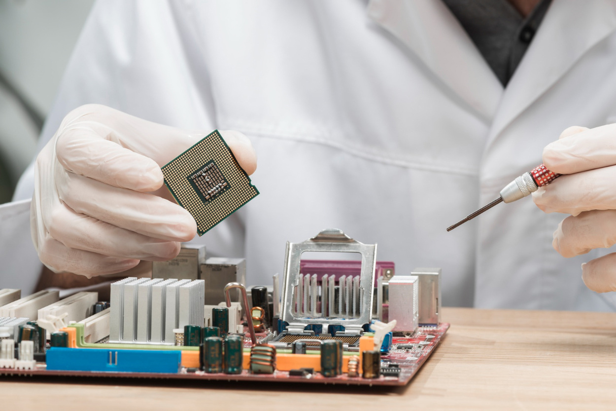
Illustrative scenario based on common patterns in mechatronic production ramps.
The prototype homed cleanly, ran its motion profiles without a fault, and held position under load. The firmware team had tuned the control loops on it for weeks. By every measure available in the lab, the product worked.
Then the first pilot batch was assembled by operators who had not designed it. Some units homed a few encoder counts off. One axis ran audibly louder than the others. Two units failed functional test, passed on retest, and nobody could say which result was true. One connector that the engineers had always seated by feel turned out to be half-mated.
None of these units was badly designed. The design had simply never been asked to tolerate variation in part dimensions, supplier lots, operators, fixtures, or assembly order. The prototype was built once, by experts, from hand-picked parts, and adjusted until it worked. That demonstrates a concept. It does not demonstrate a production process.
Teams typically assume: if the prototype works reliably and the design has been reviewed, production is mainly a matter of ordering parts and finding a factory.
In reality: a prototype shows that one assembled system can work. Production readiness demonstrates that a controlled process can repeatedly produce conforming units, built, calibrated, tested, and traced by people and equipment outside the design team.
Quick Overview
Problem: A mechatronic product that works as a prototype shows unit-to-unit differences in motion behavior, unexplained test failures, and low first-pass yield once it is built in batches.
Common causes: Tolerance chains that end at sensors and moving interfaces, assembly steps that depend on feel, missing per-unit calibration, manual firmware loading, and motion tests without defined limits or decision rules.
Where it appears: Motion platforms, robotic subsystems, servo and stepper drive products, dosing and sorting equipment, precision consumer mechanisms, and laboratory automation.
Engineering focus: Repeatable motion behavior across units, demonstrated on a pilot build rather than inferred from one good prototype.
What a Prototype Shows and What Production Has to Demonstrate
A prototype answers the question "can this work?" Production asks a different one: "will the thousandth unit behave like the first, and will we know if it does not?" A production unit can depend only on what is written down, fixtured, and measured.
| Working prototype | Production-ready product | |
|---|---|---|
| Assembly | Built by the designers and adjusted until it works | Built by trained operators from work instructions, with no undocumented adjustment |
| Mechanical fit | Works at the dimensions actually built | Works across the analyzed tolerance range of the parts |
| Calibration | Tuned by hand; values live in someone's notes | Defined procedure, stored per unit, verified independently |
| Firmware | Whatever build is on the bench | Released, versioned image loaded and read back by the line |
| Test | An engineer watches it work | Every unit measured against written limits and decision rules |
In Promwad's mechatronics development lifecycle, this is the path from a housed, functioning prototype through alpha to a beta unit that is fully functional, tested, validated, and DFM-ready, the point at which a design is ready for production transfer.
Much of production readiness is common to all hardware: DFM reviews, BOM lifecycle checks, and the documentation a manufacturer needs. Those topics are covered in the prototype-to-production transition for complex electronics and managing the hardware lifecycle from BOM to box. This article concentrates on what changes when the product moves: tolerance chains that end in a control loop, calibration of motion sensors, motion-specific end-of-line tests, and how to read a pilot build of a mechanism.
Tolerance Stack-Up in Moving Assemblies
In a mechatronic product, a tolerance chain decides not only whether parts fit but how the control system behaves. A dimension inside its tolerance can still change an encoder air gap, gear mesh, belt tension, or bearing preload, which later resurfaces as an apparent firmware problem.
Analyze first the chains that end at a sensor or a moving interface:
- Sensor-to-target distance. The air gap between a magnetic encoder and its magnet, or the offset between an optical sensor and its code disk, has to stay inside the window the sensor datasheet specifies across the tolerance range, not only at nominal.
- Center distances in gear and belt drives. They set backlash and belt tension, which affect positioning error and loop resonances.
- Shaft alignment and runout. Misalignment between motor, coupling, and load raises friction and current draw.
Worst-case analysis adds every tolerance at its limit and shows whether an assembly can fall outside its functional limits at all. Statistical methods such as root sum of squares (RSS) estimate the combined variation under stated assumptions: independent contributors, known distributions, and processes centered on nominal. RSS alone does not tell you how often an assembly will fail; that estimate needs validated distributions and process capability data, which often do not exist before production parts are made. Critical chains are therefore frequently checked both ways, and the statistical result is revisited once first production parts can be measured.
Either method is only as good as the datum scheme behind it. Drawings, inspection, and assembly fixtures should reference the same datums; otherwise the stack-up describes a part nobody actually measures. The earlier design stage can already narrow the search: sensitivity analysis before the first mechatronic prototype indicates which parameters the motion behavior depends on most, and the stack-up is where those findings meet drawing tolerances and supplier capability.
The output is a set of decisions: which dimensions are inspected, where a tolerance can be opened, where a locating feature or spring-loaded element removes the sensitivity, and what is left to calibration.
DFA and Parts Control: What Changes When the Product Moves
General DFM and DFA rules apply to every product. Moving assemblies add a few failure modes that deserve their own checklist:
- Adjustments by feel. Belt tension, bearing preload, and gear mesh set "until it feels right" do not transfer to a production line. Each needs a fixture, a gauge, or a measured value with a tolerance, or a design that makes the adjustment unnecessary.
- Orientation and sequence. Bearings, magnets, and couplings that can be fitted wrongly should be prevented by asymmetric features, not only by the work instruction.
- Cables on moving axes. Harnesses that flex in operation need cable rated for continuous flexing, a defined bend radius and routing, strain relief at both ends, and keyed connectors that an operator can seat fully and see seated.
- Parts that affect motion behavior. A replacement motor with the same frame size can have a different torque constant, rotor inertia, or cogging. A different encoder can change resolution or latency. A different bearing, grease, or spring changes friction.
The last point is where general BOM control needs a mechatronic extension. Substitutes that match on package and nominal value can still differ on the parameter the design depends on, as described in where turnkey electronics manufacturing fails without DFM and supply chain control. For motors, encoders, drivetrain parts, power stages, and anything that affects calibration, the practical rule is that no substitution happens without an engineering change and a defined regression test. When such a part reaches end-of-life in a product that is already in production, the choice between like-for-like replacement and partial redesign becomes its own decision, covered in legacy mechatronic product modernization.

Production Calibration for Motion Systems
Some variation is less expensive to measure and correct than to design out, which is the role of production calibration. Typical per-unit targets in mechatronic products are the electrical angle offset between encoder and rotor that field-oriented control needs for commutation, current-sense offset and gain, load-cell zero and span, IMU bias and axis misalignment, homing and end-stop references, and temperature-sensor offset.
Calibration should not mask defects. A coefficient near the edge of its plausible range usually points to a misassembled unit rather than an unusual one. Each coefficient needs acceptance limits, and a unit outside them should be rejected and investigated rather than calibrated into specification.
Calibrate, then verify independently. The stored value should be checked by a separate measurement, preferably at a different operating point, so that a wrong coefficient does not pass the same test that produced it.
Treat calibration data as product data. Coefficients belong in non-volatile memory with an integrity check and a format version, recorded against the unit serial number, and recoverable when the unit returns for service. Reference instruments on the station need their own calibration interval.
In Promwad's studio-grade direct-drive turntable design, the firmware processes encoder data in real time to extract wow and flutter, so that verification can move upstream to the mechanical assembly stage instead of relying on external analyzers at the end of the line. The design package is ready for prototyping and its performance targets are still to be validated on prototypes. Built-in measurement of this kind can reduce the external instrumentation a production station needs.
Firmware Programming, Configuration, and Provisioning
On the bench, firmware is whatever build the engineer loaded last. On a production line, loading it is a process step with its own failure modes, cycle time, and records. A robust flow keeps four stages apart:
- Programming. Bootloader and application are loaded through a programming interface (SWD, JTAG, or a vendor bootloader) from a released image identified by version and hash, never from a developer's build folder.
- Configuration. Per-unit data is written: serial number, hardware variant, regional settings, network identifiers from an allocated range, and calibration coefficients.
- Provisioning. For connected or security-relevant products, unique identities, keys, or certificates are injected with controlled tooling, since key handling on the factory floor is a common weak point; see secure provisioning for industrial devices.
- Access control and read-back. After tests pass, debug access and flash readout are restricted according to the product's security and service policy, then versions, configuration, and checksums are read back and logged. The policy should define how returned units are diagnosed and recovered, so that locking does not make RMA analysis impossible.
The sequence matters: restricting access before functional test is complete makes failed units harder to analyze. The image itself must also be reproducible. A reproducible firmware build from a controlled baseline is what makes a version number mean the same binary at the factory, in the field, and at the service center.
Motion-Specific End-of-Line Testing
End-of-line (EOL) testing is not a shortened design validation. Design validation shows that the design meets its requirements, usually on a sample and often destructively. EOL testing shows that a particular unit was built correctly, on every unit, within a cycle time the line can sustain. It should therefore target the defects that assembly and supply variation can realistically introduce:
| Test layer | What it catches | Typical method |
|---|---|---|
| Board-level structural test | Solder defects, missing or wrong components, opens and shorts | AOI, in-circuit or flying-probe test; JTAG boundary scan where the devices and scan chain support it |
| Internal communication | Unmated or miswired connectors, dead nodes | Read-back from every board, drive, and sensor on internal buses |
| Sensor plausibility | Wrong sensor, poor mounting, failed calibration | Readings at known reference conditions; cross-checks between sensors |
| Motion and actuation | Binding, misalignment, wrong gearing, reversed phases | Full-range motion, homing repeatability, no-load current and following error per axis |
| Safety functions | Broken safety chain, miswired stops and interlocks | Emergency stop, limit switches, safe torque off where fitted |
| Electrical safety (where required) | Insulation and protective-earth defects | Hipot and earth continuity when the applicable standard requires routine tests |
| Identity and configuration | Wrong firmware, variant, or calibration | Read-back of versions, checksums, serial number, and calibration data |
Boundary-scan coverage depends on which devices implement IEEE 1149.1 and on how the scan chain is designed, so it is planned in the schematic, not assumed from the processor.
EOL testing should not try to replace reliability testing: long-duration cycling, stress, and aging belong to design validation and sample-based production audits.
Motion data is particularly informative here. No-load current and following error per axis respond to friction, misalignment, and binding, can usually be captured during a homing move, and, stored as values rather than pass/fail flags, help reveal supplier or process drift.
Test Fixtures, Decision Rules, and Traceability
Fixtures. A fixture has to locate the unit repeatably and make every electrical, mechanical, and pneumatic contact reliably without damaging the product; excessive probe force on a bed-of-nails fixture can crack ceramic capacitors or lift pads. Contacts wear and need scheduled replacement. Frequent false failures teach operators to retest until units pass, and the test gradually stops protecting anything.
Limits and decision rules. Limits start from the product specification. For results close to a limit, the test needs a documented decision rule that accounts for measurement uncertainty; guard-banding is one common way to implement it, and ILAC-G8 describes the options used in conformity assessment. Before release, the test should be proven in both directions: a golden unit that passes consistently, and deliberately faulted units, such as a missing connector, a reversed motor phase, or a wrong sensor, that fail. A gage repeatability and reproducibility study on key measurements shows whether the station can distinguish good units from bad ones.
Traceability. Each unit should leave the line with a record linking its serial number to its main assemblies, firmware image hash, configuration and calibration data, measured test values, fixture and station, date, and, for critical components, the supplier lot. When a field problem has to be contained, this record lets the manufacturer narrow the affected population; without it, containment typically has to cover a much wider range of units.
Promwad develops production test benches and acceptance criteria, covering firmware installation, ICT and JTAG-based testing, and functional test systems.
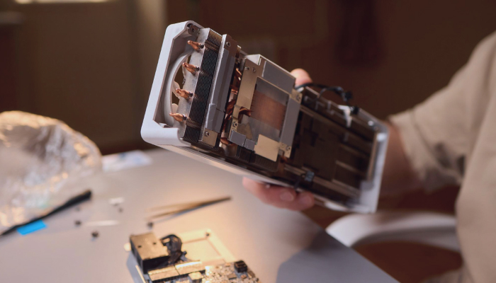
Industrial Control Panel: Designed for Test Before the First Board Was Built
For a large European developer and manufacturer of industrial controllers, Promwad ran the full development of an industrial control panel, covering industrial, mechanical, hardware, and software design on a TI Sitara ARM-based processor, together with a custom functional test bench:
- Component requirements included an MTBF of at least 125,000 hours and replacement analogs available from other vendors; the element base was adapted to the manufacturing site to reduce cost.
- The circuit was designed with JTAG boundary-scan testing in mind, so that assembly defects can be detected at early stages of manufacturing.
- The test bench flashes NAND memory first, then checks the processor, memory, display, keypad, and external connectors. It detects which build option is fitted, runs the matching procedure without operator intervention, and logs errors.
- Following assembly testing, thermal modeling, and boundary-scan checks, and with a complete design documentation set, the client certified the devices and launched mass production.
Full engineering write-up: → Industrial Control Panel Development
Pilot Build: Reading a Mechanism Before Volume
A pilot build is the first time the product meets its real production process: production-intent parts, the actual assembler, trained operators, and the real fixtures and test software. A useful pilot collects first-pass yield per station, a failure Pareto by station and test step, a rework log, real cycle times, the false-failure rate of each fixture, and first article inspection of parts from production tooling.
The key discipline is to classify each failure before fixing it, because each category has a different owner:
- Design: no margin for normal variation, such as a tolerance chain that closes, a loop tuned on one motor, or a thermal limit reached on a warm day.
- Parts: a supplier lot or a substitute that behaves differently from the prototype parts.
- Process: an ambiguous assembly step, an uncontrolled torque, a connector that is not fully seated.
- Test: a wrong fixture, limit, or script while the unit itself was fine.
When a cause crosses disciplines, for example an axis that oscillates only on some units, a synchronized set of encoder, current, and supply measurements usually settles it faster than a debate between teams; debugging mechatronic failures across mechanics, electronics, and firmware describes that method.
Tooling iterations belong here too. In Promwad's gas analyzer enclosure project, the injection mold was refined across three sample iterations to fix an uneven seam and the feel of the buttons in cold weather before the client launched an initial batch of 5,000 enclosures.
A successful pilot build reduces risk; it does not eliminate it. Volume brings new supplier lots, new operators, fixture wear, and conditions the pilot did not see.
Handing Over to Production
Beyond the usual drawings, fabrication data, and controlled BOM, the transfer package of a mechatronic product needs its adjustment specifications, calibration procedure with coefficient limits, firmware release with programming and access-control steps, EOL test specification with fixtures, limits, and decision rules, and the traceability requirements described above.
Two Promwad drive projects show the effect. In the DC/AC servo drive project, adaptation to manufacturing and preparation of all necessary documentation allowed the client to launch production of the first batch independently. For the stepper motor driver with EtherCAT support, the client received a production-ready driver built on widely available components and, with the documentation in hand, could select a manufacturer independently.
On certification: pre-compliance testing and a complete technical documentation set prepare a product for conformity assessment but do not replace it. The manufacturer remains responsible for compliance, and a notified body or other third party is involved only where the applicable legislation requires it. Promwad supports this with pre-compliance testing, documentation, and guidance.
How to Approach Production Readiness

Define what 'the same' means
Write down, with numbers, the motion behavior and performance every unit must meet.

Find where variation enters
Analyze tolerance chains that end at sensors and moving interfaces, remove adjustments by feel, and restrict substitutions on motion-critical parts.

Design the production process as one system
Fixtures, calibration, firmware loading, EOL tests, and data records share fixture time and the unit record, so design them together and prove them with golden and faulted units.

Run a pilot build and classify every failure
Close causes by category and freeze the transfer package once the remaining failure modes are understood.
Real Trade-offs to Expect
- Tighter tolerances vs. calibration. Tight tolerances reduce the need for calibration but raise part and inspection cost. Looser parts with calibration can lower part cost, but they add a station, cycle time, and a per-unit data record; which option costs less depends on volume and on how stable the calibrated parameter is.
- Test coverage vs. cycle time. Every test step catches something and uses line time. A well-scoped EOL test covers the defects assembly can realistically introduce and leaves design-level checks to sample audits.
You May Be Facing This If:
- Your prototype works, but nobody outside the design team has assembled one.
- Units from the same batch move differently, and the difference disappears when an engineer reassembles them.
- Some units fail functional test and then pass on retest with nothing changed.
- Firmware is loaded from a developer's laptop, and nobody can say which binary is on a shipped unit.
- Your manufacturer asks which motors, encoders, or bearings may be substituted, and there is no written answer.
How Promwad Helps
Promwad treats production readiness as engineering work across mechanics, electronics, firmware, and test, done by the team that can also design the product:
- Production-readiness review of an existing prototype: tolerance chains, DFA, parts control, calibration, firmware flow, and test strategy.
- Mechatronics design from architecture through prototype, alpha, and beta to a DFM-ready design and production transfer.
- Production test benches, ICT/JTAG and functional testing, with acceptance criteria and test software.
- Transfer documentation and pre-compliance support, with transfer to Promwad's manufacturing partner or to a plant you nominate.
Have a working prototype that now has to become a product?
FAQ
What is the difference between a working prototype and a production-ready product?
What should an end-of-line test check on a mechatronic product?
When should production calibration be used instead of tighter tolerances?
Related Articles in This Series
- Simulation Before a Mechatronic Prototype: What CAE Can Evaluate and What Hardware Must Confirm: before the first prototype.
- Debugging Mechatronic Failures Across Mechanics, Electronics, and Firmware: during integration and in the field.
- Legacy Mechatronic Product Modernization: What to Keep, Replace, or Redesign: for products already in production.
Related Promwad Expertise
- Industrial Control Panel Development: single-sided board, JTAG boundary scan, and a test bench that flashes firmware and runs functional test automatically.
- DC/AC Servo Drive Design for Production: a drive adapted to manufacturing, with documentation that let the client launch the first batch independently.
- Stepper Motor Driver with EtherCAT Support: a production-ready driver on widely available components.
- Studio-Grade Turntable Built to Verify Itself: embedded wow and flutter measurement designed to move verification upstream.
- Gas Analyzer Enclosure Manufacturing: three mold sample iterations before an initial batch of 5,000 enclosures.
Prepare Your Prototype for Production
Share what the product does, how many units you plan to build, and what happens today when someone outside the design team assembles it. We will help define what has to be validated before production transfer.