


Industrial Control Panel Development
Client
A large European developer and manufacturer of industrial controllers and other automation equipment.
Challenge
The client turned to Promwad to develop an industrial control panel for its equipment product line.
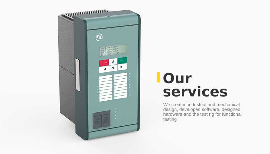
Project tasks:
- industrial design
- mechanical design
- hardware design
- software development
- the test rig for functional testing development
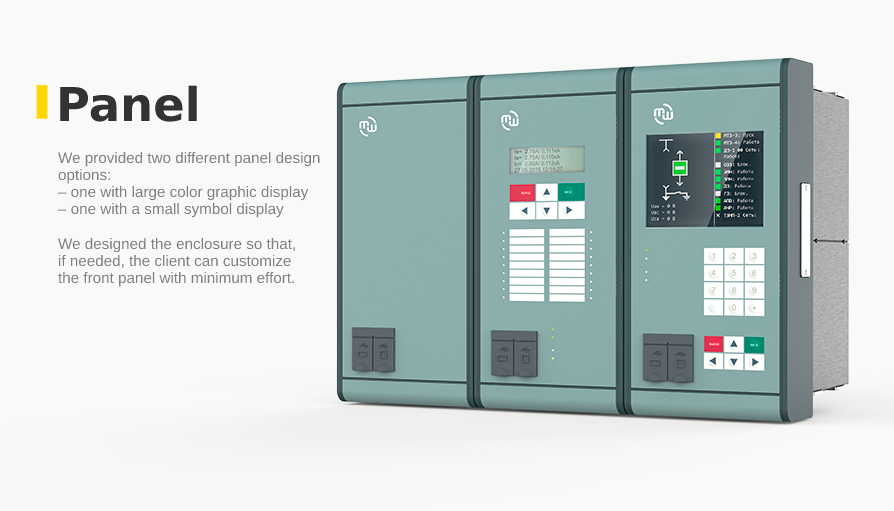
We were to provide two industrial control panel design options:
- one with large color graphic display
- one with a small symbol display
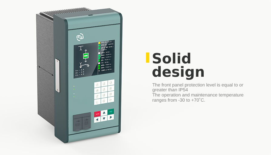
This project required high operation standards:
- Operation and maintenance temperature range is from -30 to +70˚C
- The total average MTBF of the device is at least 125000 hours.
- Service life — at least 25 years
- EMC testing: operation at average electromagnetic field strength according to CO34.35.311-2004
- Front panel protection level is equal to or greater than IP54
Solution
1. Industrial Design
We carried out mechanical design in a way to reduce risks. To do so, we designed a display panel 3D model. After that, we arranged the printed circuit board layout, considering the enclosure design requirements. In the end, we checked and paired the 3D models of the enclosure and the board.
It was easy for us to make parts' layout and test the assembly thanks to ready-made 3D models. However, the test results revealed the need for some design modifications.
Our designers modified the front button panel: now it's possible to select its availability option, as we moved the buttons and LEDs to an independent board. That board is connected to the panel board via a pin connector. This way of connection provides safe transportation even in harsh conditions like vibration.
All in all, our experts made it possible for the customer to choose the desired configuration and layout of the control buttons and LEDs.
After final design approval, we made prototypes and developed design documentation for mass manufacturing launch.
2. Mechanical and PCB Design
Circuit design considered the following requirements to the element base:
- MTBF is at least 125000 hr;
- availability of replacement analogs from other vendors.
We adapted the project element base for the manufacturing site to ensure cost reduction. We implemented a printed circuit board with a single-sided mounting and in a minimal form factor for the same purpose.
The board is based on a Sitara ARM-based processor developed by Texas Instruments.
The DDR2 chip with 128 Mbytes represents the operating memory. The RAM is NAND Flash 128 Mbytes.
We designed the printed circuit board with two features in mind:
- availability of two assembly methods: with the installation of an eight-digit OLED screen or a full-fledged TFT display;
- placing the element base on one side of the board to optimize the cost of mass production.
PCB designers checked the integrity of high-frequency signals and compliance with EMC requirements. For this purpose, we calculated wave and differential resistances.
The printed circuit board architecture is the one with the lowest manufacturing cost.
The DDR bus circuits were tuned to match the high-speed links.
The secure connection of external devices has made galvanic isolation of the corresponding ports.
We equipped the board with an installation place for a shield to protect sensitive elements from external forces.
Table 1. Device board specifications
| Board type | Digital |
| Layers count | 4 |
| BGA-enclosures | 2 BGA (CPU — BGA361, DDR2 — BGA100) |
| Size, mm | 242 x 118 mm |
| Number of circuits | 1534 |
| Number of solder points | 2151 |
| Differential pairs | 3 (1xCLK_DDR2, 2xUSB) |
| Components number | 532 |
| CPU | TI Sitara |
| Memory: |
|
| Special features | 1 х USB 1.1 HOST Isolation 1 х USB 1.1 Device Isolation 1 х UART 1 х RGB565 1 x RS485 Isolation 1 x JTAG 1 x LCD interface 4x8 keyboard matrix 24 x LED outputs |
While designing the circuit, we considered the requirements of peripheral JTAG boundary-scan testing. In addition, we provided the possibility of post-production inspection of the board for the quality of the component base assembly.
Thus, we have increased the reliability of the final product — the client is able to detect errors at the early stages of the manufacturing process.
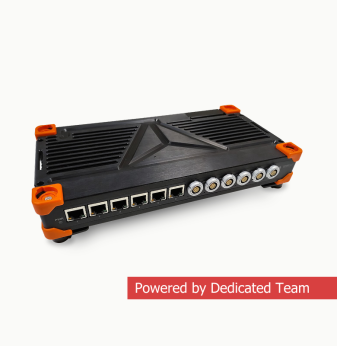
3. Functional testing bench
We developed hardware, software, and documentation for NAND-memory flashing and display board functional testing. The software displays the detection of errors that occurred during the operation.
Flashing is performed at the first stage of operation, followed by functional testing.
The software automatically detects which option is active and starts the appropriate testing procedure.
As a result, the customer received a set of test bench equipment.
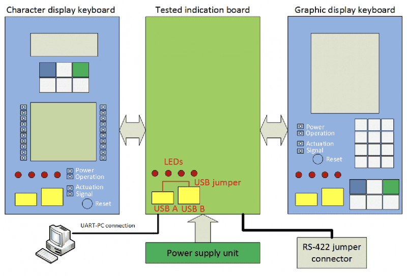
3.1 Functional testing software
The software provides a complete functional check-up of the display board: scans the processor, memory, display, keypad, external connectors. The test process is shown on display.
Note that the whole process runs "on-board": the figure below demonstrates this.
Test bench benefits:
- The capability of board flashing from the assembly stage
- Perfect testing process visualization
- Tests tun automatically: without operator intervention
- Error logging
- Easy scalability
Business Value
The designed enclosure has an IP54 level of protection. The device has passed the required tests for compliance with electrical safety requirements. At the same time, that did not affect its appearance or complexity: the device is easy to assemble and has a small thickness (about 2.5 cm).
We designed the enclosure so that, in case needed, the client can customize the front panel with minimum effort.
The schematic design met the needs of the customer both from a functional and technological point of view.
The printed circuit board was designed with minimal manufacturing cost and the ability to connect different types of graphic screens and controls.
We conducted assembly testing, thermal modeling, and other types of tests, including the JTAG boundary-scan. Besides, we performed the compliance check-up of the documentation set.
We have developed a complete set of design documentation for all device elements. It complies with the necessary regulatory documents and standards.
Thanks to the Promwad Manufacturing team, the client successfully certified the devices and launched mass production.