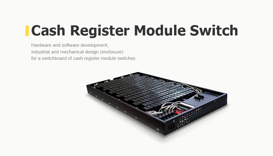


Hardware & Software for a Switchboard of Cash Register Module Switches
Client
A European technology company that automates retail and service industries using its own devices and software.
Challenge
We were commissioned to develop hardware and software for a cash register module switch. We were also responsible for the design of the device enclosure for a 19" rack that is 1.5 U high. In terms of electronics and software, the new system should be a set of basic boards, modules, and cable connections:
- Two boards for the segment and the cash register switch aggregator.
- AC/DC power supply with onboard connection cables.
- External connectors, LEDs, buttons and cables for Ethernet and power.
The device must work correctly at temperatures from +10° C to +30° C and be tested for resistance to electrostatic discharges on connectors and external current-carrying elements.
Solution
-
Hardware design
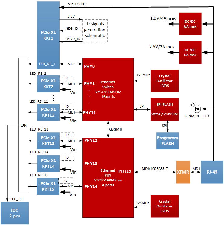
Figure 1. Block diagram of the cash register switchboard segment
We have designed a device based on the VSC7421XJG-02 switch from Microchip with 16 ports. To provide additional ports for the Ethernet physical layer, we installed a four-port VSC8514XMK chip with a QSGMII interface on the segment card to connect to the network switch.
We also installed 15 PCIe slots on the segment board to connect 15 cash control modules and an unshielded RJ-45 connector with LEDs to connect to the aggregator (uplink to the segment switch). Transmission speed and pin assignment meet the 100BASE-TX and TIA/EIA-568-B standards, respectively.
The segment board itself was powered by the aggregator at 12VDC. The maximum consumption is 21 W with all 15 modules installed (their average consumption is 0.6 W, and the peak consumption is 0.7 W).
Voltage is supplied via two free pairs of RJ-45 connectors (according to pin assignment for 100BASE-TX and TIA/EIA-568-B): one of the pairs as +VCC (12VDC), the other one as 0V (GND). It is allowed to "hot plug" the segment when power is present on the RJ-45 cable connector from the aggregator.
We installed a 16 MByte SPI FLASH IS25LP128-JLLE chip to boot the network switch. We placed a connector to connect an external SPI FLASH programmer on the segment board.
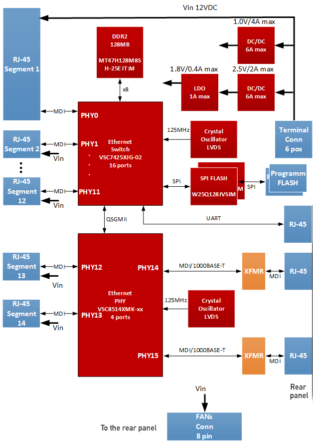
Figure 2. Block diagram of the aggregator
The aggregator board was designed on the VSC7425XJG-02 segment switch chip (Ethernet Switch L2) by Microchip with 16 ports.
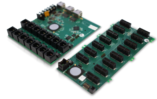
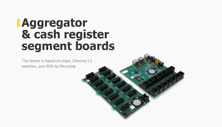
Figure 3. The aggregator and cash register segment boards
We have installed 14 RJ-45 connectors on the aggregator for connecting 14 segments. The segments are powered directly, without conversion or switching, from the AC/DC power supply connector through the aggregator board via Ethernet cables.
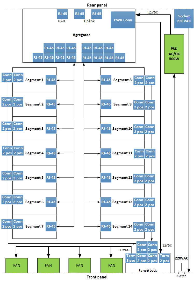
Figure 4. Block diagram of the complete device
-
Software development
- Segment
We developed the Ethernet switch software on the Microchip VSC6811 SDK Web Config Software Package. It is an application to control the functions of the VSC7421 switch.
The software runs on the Microchip VSC7421 switch chip's internal 8051 processor and is stored in the switch's internal SPI Flash memory.
The software allows three methods of control:
- command line interface;
- web interface;
- SNMP.
- Aggregator
We have developed the software for the VSC7425XJG-02-based Ethernet switch using the Microchip SMBStaX software package.
The software is executed on the internal MIPS32 processor of the switch chip and is stored in its internal NOR memory. It supports the STP and RSTP protocols.
The switch software allows the network administrator to select one of three control methods with an extensive feature set:
- command line interface;
- web interface;
- SNMP.
The switch stores its configuration in several CLI text files.
The software also supports DHCP, which ensures that all segments and cash registers receive an IP address.
The web-based management interface of the software allows remote configuration and control of the switches. It is divided into groups for the following tasks:
- switch function configuration;
- monitoring of the configured functions with the automatic update;
- running supported diagnostics.
To help the network administrator, our engineers developed reference pages.
The basic functions of the L2 switch:
- a dynamic table of MAC addresses;
- static table of MAC address;
- IEEE 802.3ad channel aggregation;
- static aggregation;
- Link Aggregation Control Protocol: LACP exchanges LACPDU with the remote switch and automatically generates aggregation;
- spanning tree.
-
Enclosure and mechanical design
We were also responsible for the design of the device enclosure. The case with the dimensions 64x426x832 was made of 1.5 mm thick sheet metal.
The upper lid was divided into two unequal parts to increase rigidity. The large part of the cover is removable and provides easy access to internal components for quick replacement. The small part is stationary, it supports the movable cover and protects components that are not subject to frequent replacement.
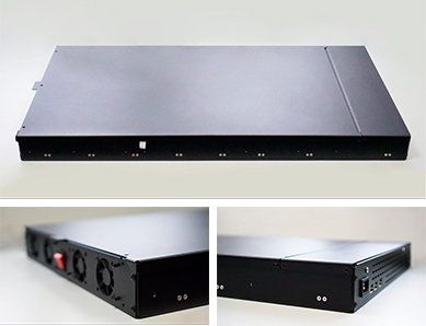
Figure 5. The cash register enclosure
The front panel is designed as an overlay: it performs a decorative function and protects the ventilation holes and power buttons from accidental pushing. On the front panel, there are handles to slide the device out of the rack.
Four fans and a perforated enclosure are used to cool the device.
Business Value
Our client received a new hardware and software solution for its product line designed for retail, HoReCa, transportation, logistics, and utility sectors. The new switches will be used in the medium and large business segments because they allow connection of up to 15 cash register modules and are housed in standard 19" racks. Production of the devices will be established based on the Microchip switches.


