3D Ultrasonic Tomography for Non-Destructive Material Testing Powered by FPGA

We launched the development of an FPGA-based controller for 3D ultrasonic tomography that will be used for non-destructive testing, visualisation, and detection of defects in metal and concrete building structures in real time. By incorporating the FPGA into the system, our customer plans to improve inspection quality and bring the NDT to a new level with improved spatial resolution and contrast.
The System Design and Key Features
The 3D ultrasonic tomography system consists of the following components:
- phased array transducer;
- MEMS-based (microelectromechanical system) acoustic antennas;
- signal processing unit;
- UI interface for configuring the system and 3D data visualisation.
Ultrasonic inspection involves sending and receiving pulsed waves from a transducer that reflect off the back surface of an object or a defect within inspected materials. The diagnostic device then displays these reflections as signals; their amplitude indicates the strength of the reflection, and the time required for the signal to return indicates the depth of the defect.
For tomographic imaging, a phased array transducer emits ultrasonic waves received by several acoustic antennas. The system processes the received signals to generate 3D images of scanned objects.
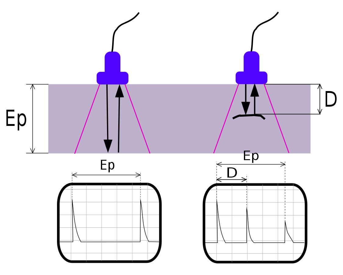
Operating principles of the ultrasonic 3D tomograph. Source: Romary, Wikipedia, CC BY-SA 3.0
- 10x increased angular resolution of imaging.
- Single emitting ultrasonic transducer array and multiple receiving channels.
- 10x increased spatial resolution in solid materials — 0.1 mm vs. the usual 1 mm; the resolution range is configurable depending on the selected frequency of the ultrasound.
- Improved beam steering frequency: a high frequency allows for faster real-time defect detection. Most ultrasonic 3D tomography systems for NDT operate in the frequency range of 400–500 kHz. Moving from 2D imaging to 3D is challenging as the system must operate at frequencies up to 10 MHz range.
As a result of the project, our client will receive an improved 3D ultrasonic tomography system with increased resolution and FOV for non-destructive testing, ensuring high accuracy and safety.
Want to improve your non-destructive testing system with FPGA? Drop us a line to discuss the details:
Our Case Studies on FPGA Design


