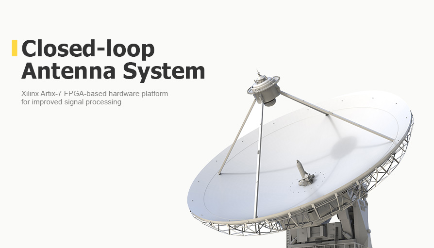

Closed-Loop Antenna System for Improved Satellite Signal Reception
Project in Nutshell:
We were commissioned by a major manufacturer of mobile satellite antennas to develop algorithms for an Artix 7 FPGA by Xilinx/AMD to improve the final signal for a vehicle-mounted antenna. We achieved a speed of 12 microseconds to generate corrections to the antenna performance — 3 microseconds faster than the target value.
As a result, our client can remotely tune the antenna and provide a high-quality satellite signal in near real-time.
Client & Challenge
Before the FPGA implementation, signal analysis and correction factor generation were done on a CPU and its response speed was insufficient: it took more than 15 microseconds from the command receipt to recalculate the factor to the output of the new data to the antenna.
Solution
- Our engineers implemented basic functions according to the technical specifications and handed them over for laboratory and field testing on the client's side.
- After the testing, our client requested the implementation of some additional features.
1. Concept Development
Our engineers described the algorithms to be implemented in the FPGA to calculate the main parameters of the phased array antenna in a fixed-point format.
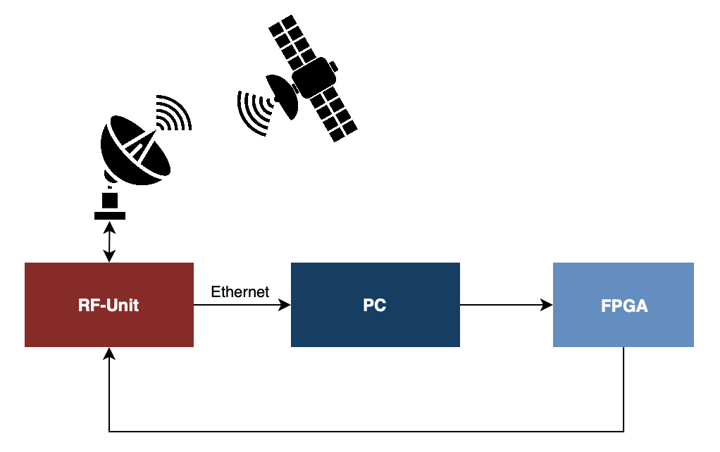
Schematic diagram of the signal reception system and correction factor formation
Our solution operates in the following way: the antenna receives a signal evaluated by algorithms. These algorithms generate data for the FPGA that generates a correction factor to improve the communication quality and sends it to the antenna, which applies the signal changes. The computer monitors the status, selects a new correction factor, and sends it to the board.
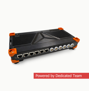
2. Hardware Design & Firmware Development
We developed the hardware platform based on the AMD/Xilinx Artix-7 FPGA. The firmware, based on the data received via the SPI interface, calculates the main parameters for the antenna phased array. All calculations are done in fixed-point format. After this analysis, the obtained values are transmitted via output lines in the SPI format. The PC receives the signal, evaluates it and outputs four signal parameters sent to the board. Based on this information, we recalculate the correction factors in the FPGA: phase, amplitude, phase correction, and amplitude correction. This data is sent to the RF part via the SPI interface. According to the task, we have 15 microseconds to start issuing the calculated data after the four parameters come. After entering the first estimated data into the RF part, it must come out no later than 15 microseconds (actually, it is 12).
Business Value
More of What We Do for Satellite Communications: