Cooling Electronics: Thermal Modelling in Enclosure Design
A common electronic device consists of an enclosure or case and internal components that emit heat when they work. And that's where the conflict comes in: manufacturers try to make their enclosures smaller (cheaper and more convenient), but a compact enclosure prevents heat dissipation. The growth of computing power exacerbates the problem: the electronics get hotter, leading to failures. How to ensure sufficient cooling in such conditions while designing enclosures new mass-produced devices? Let's go through the different types of heat dissipation together, considering natural convection, forced cooling with fans, and liquid cooling systems.
Contents
- Introduction
- Case study #3: A protective shield as a radiator
- Case study #4: Heat dissipation to an enclosure
A mechanical designer is whom you need for the detailed design of the cooling system and the proper layout of the device: they perform a virtual simulation of airflows and determine the temperature of your working and warming up electronics.
While choosing the type of cooling, designers and hardware engineers consider the maximum allowable temperature of the components and operating conditions.
The simplest method of heat dissipation is the air-cooling method using heat sinks and fans. This is a low cost but has several disadvantages:
- high thermal resistance,
- low ambient temperature,
- increased noise level.
It is not always possible to use forced or natural convection cooling. For example, this method is unsuitable for enclosures with a high degree of protection against dust and moisture (IP) or maintenance-free enclosures, i.e. non-dismountable or those installed in hard-to-reach places.
Increasing the efficiency and speeding up the cooling process can be achieved by cooling with heat pipes. This method uses an aluminium heat sink and a base with copper tubes. This technology has significant advantages: it optimally dissipates heat, occupies a minimal volume, generates no noise and requires no maintenance. But remember that it increases the complexity and the cost of the device.
For power electronics, the liquid cooling method is used. This system is efficient and reliable, occupies a small volume, does not create noise, and significantly increases costs and complicates maintenance (there is a risk of fluid leakage). Also, this method requires a compressor.
Below we will consider examples of different methods of air cooling with natural and forced convection.
Natural convection cooling
Let's start with natural convection cooling within an enclosure, the most economically feasible method of heat dissipation.
Case study #1: material selection and enclosure perforation
As an example, we will take a device designed for our customer. He could choose metal or plastic as a primary material for the device enclosure. After doing thermal calculations, it became clear that there is no need to dissipate heat on the enclosure, so we do not need metal. We can use a cheaper and more practical option – plastic + standard heatsink. And now we need to answer an important question: where to place holes in our enclosure and how many of them to ensure passive cooling of electronics? This question can be answered by calculations, taking into account the heating of electronic components.
Let's look at the comparative models of passive cooling for the following options:
Please note that the average temperatures are given in Celsius degrees in the first column with numbers. For the CPU, they go from 119.62 degrees to 129.3 °C with different types of perforations.
Calculation models help you choose the best enclosure model. In our case, it is the second one, with large perforations on the bottom.
As you can see, not always the most apparent solutions turn out to be so in practice. It could seem that complete perforation will provide the best cooling, and the worst ones will be with no perforation at all. But modelling lets you know the honest answer.
Case study #2: Double enclosure for convection
Below is another example of natural convection cooling. The mechanical design of the enclosure consists of two parts: the inner part with multiple perforations along the entire contour for free cooling airflow and the outer enclosure, which is decorative, with perforations only on the back.
Internal device enclosure
A device with a double enclosure, assembled
The gap between the inner and outer decorative housing ensures unobstructed convection.
Cooling by thermal conduction
Thermal conduction cooling uses direct metal-to-metal contact between two parts. The heat from heated components is transferred to the outer surfaces of your heat-dissipating enclosure (or its parts) by thermal conduction.
Case study #3: A protective shield as a radiator
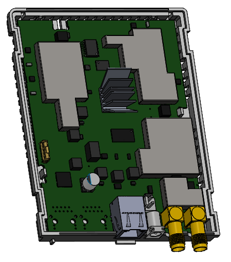
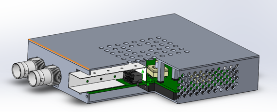
Let's see how thermal conductivity and selection of materials for enclosures work in practice. When we designed an industrial switch, we used an unconventional solution to handle heat dissipation and protect a printed circuit board from interference. Our mechanical designer suggested using a composite shield on one of the boards to solve both problems – heat dissipation due to thermal conductivity and protection from interference.
This screen was made of aluminium alloy by milling. Milling allowed us to create a metal surface with the correct parameters and ensure close contact with the heated elements. But for optimal heat transfer, we used another component between our enclosure and electronics components– special thermal pads with a high thermal conductivity coefficient.
Protective shield for heat dissipation and interference
Case study #4: Heat dissipation to an enclosure
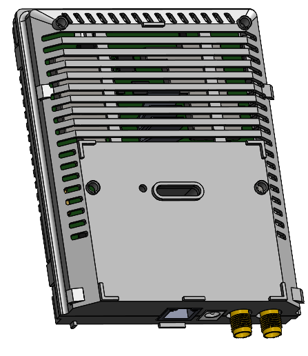
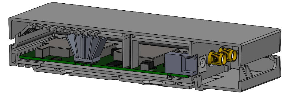
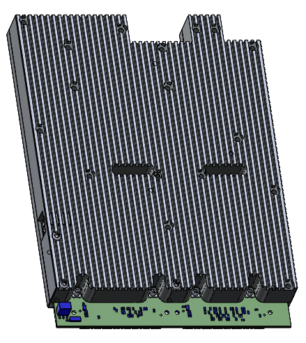
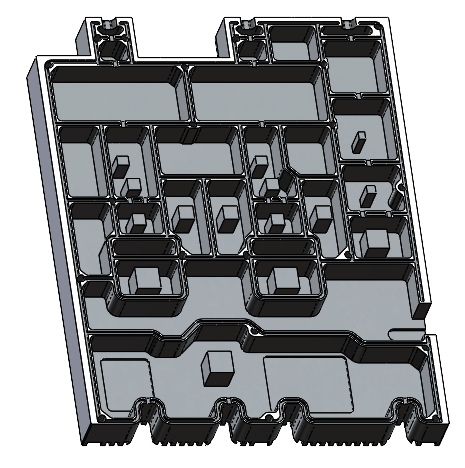
Sometimes not only tubes or screens are used for cooling, but the entire device enclosure takes the "heat shock". Of course, the best material for this task is aluminium.
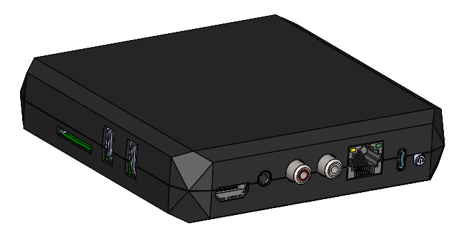
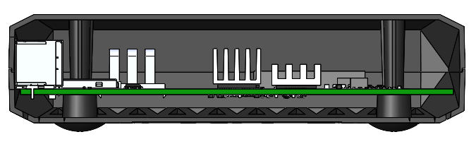
Below is an example of such a design. Our thermal modelling results showed that one standard heat sink was insufficient to dissipate all the heat, so we designed an additional aluminium enclosure.
Enclosure for heat dissipation from heated components
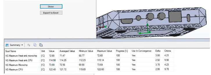
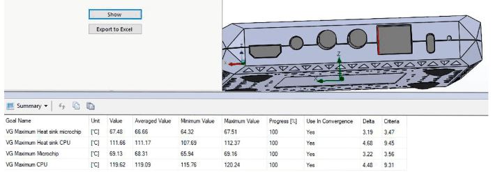
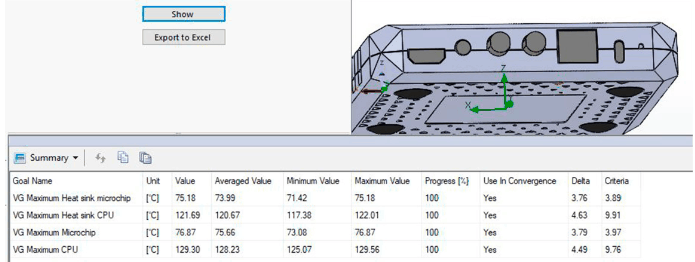
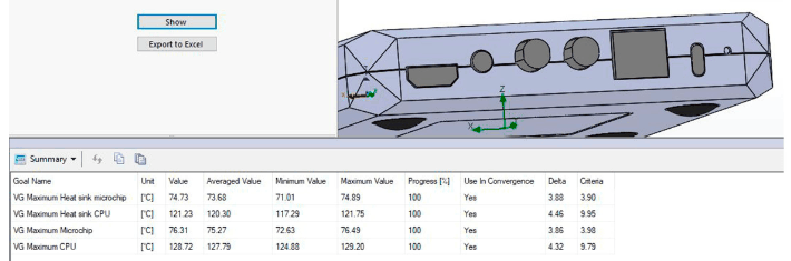
To increase natural air convection, we added holes on the sides and top edges of the enclosure:
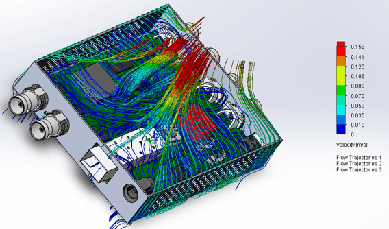
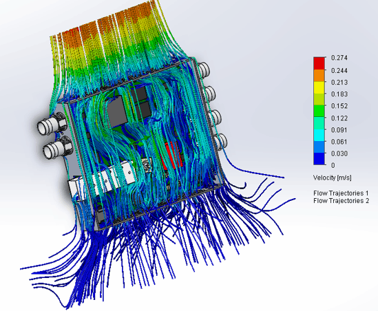
Airflow distribution when the enclosure is horizontal or vertical
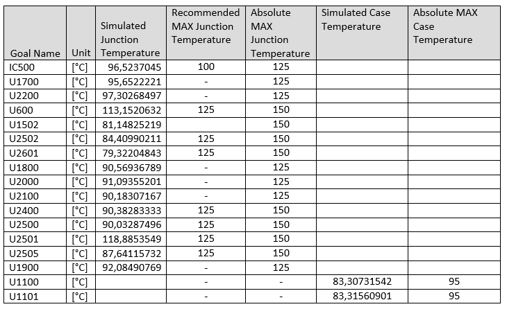
Comparative table of calculated and maximum recommended temperatures
Comparing the simulation results with the data from the component data sheets, we see that this cooling method maintains the temperatures of the components of the device within operating ranges.
Forced convection cooling
So far, we have covered natural convection for cooling, now let's look at forced convection, a more expensive but more common method of dissipating heat from electronics.
For forced cooling, hardware engineers and mechanical designers use fans.
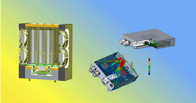
Case study #5: Cooling a device with 100+ boards
Let us see how this works in the following case study: we have designed a complicated industrial X-ray processing machine consisting of an array of over a hundred printed circuit boards arranged in rows in cassettes. The density of sensors is about 4,000 pieces.
During the initial design phase, a thermal calculation to determine the optimum layout of components on the board, board-to-board clearances, supply air temperature, and enclosure design. As a result, we selected the optimum design out of 20 iterations.
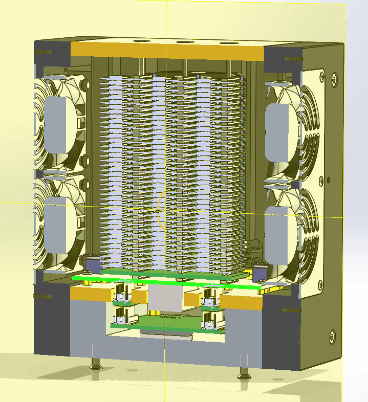
The device enclosure with installed fans
Thermo-modelling helped to identify and correct areas of concern in your design (and we have found and corrected them in our design, too ). In our case, it was necessary to redirect the flow from the back of the device to could go through the PCB area. It was also essential to change the position of the board-to-board connector so that it didn't obstruct the airflow.
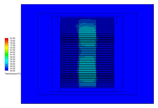
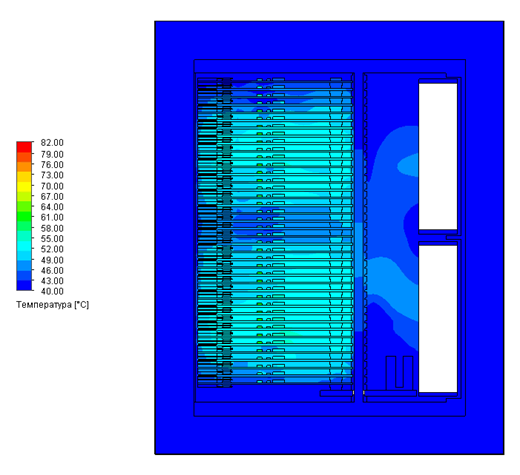
Temperature slices in the board area
The result: the average temperature spread over the sensors was ~12°C, and the maximum temperature in the sensor area was kept at ~55°C. The fans, combined with the optimum design of the chassis and sufficient distance between the boards, made it possible to ensure the effective cooling of such a complex device. This example clearly shows why forced cooling remains so popular in industrial applications with powerful user devices.
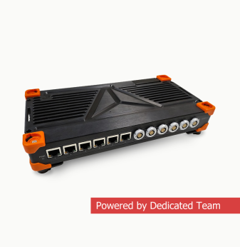
Case study #6: Cooling a 1U switch cabinet
In the last example, we will show how thermal modelling works for projects with combined cooling, where both conduction and forced convection are used in the initial design phase. So, the task is to design a universal 1U enclosure for various modifications of an industrial switchboard. The right choice of enclosure layout was of great importance. We did about 30 iterations of thermal modelling. The calculation helped determine the location of heat sinks and fans, the number of fans, the right location for the power supply, the components on the board and the perforations on the front part of the enclosure.
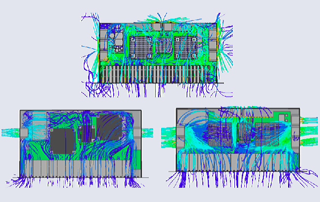
Elaboration of the internal layout of the industrial switchboard
As a result, the project was implemented in this way:
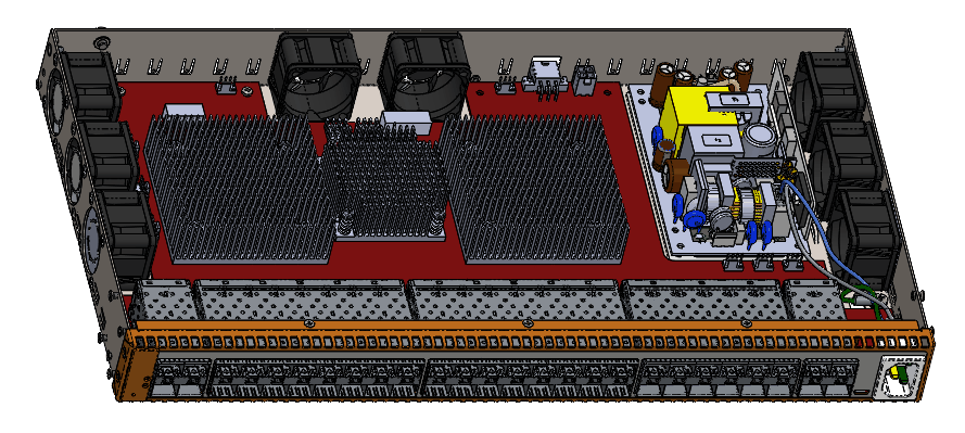
Cooling system: 8 fans and 3 aluminium heat sinks
Configuration “a cooler + a heatsink” is very familiar to desktop computer users. Those who have assembled their hardware may have noticed the different thermal interfaces: thermal paste and thermal pads between the chips and the heatsink, used for more efficient heat dissipation. Maybe someone is reading this article from their gaming computer with a fancy liquid cooling system. :-) And all these methods and components for dissipating heat from electronics have in common one crucial tool used at the initial design stage – this is term modelling and analysis. It helps you to select the enclosure material, the layout of components on the board, and the optimum system for cooling the electronics. As a result, it also customises the appearance of the device.
Conclusion: calculating the temperature characteristics of circuit boards and the entire device is an integral part of the design of modern mass-produced electronics, which helps manufacturers to reduce the risk of failure and save money and time.
Our projects