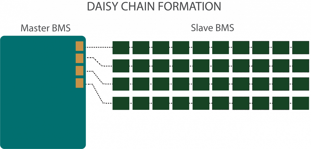
96-cell scalable Battery Management System for EV and HEV application
- Project Overview
Client
A European automotive company.
Challenge
To design a scalable Battery Management System (BMS) for easy adoption to any battery pack size needed with fast time to market and automotive graded hardware.
Solution
Our team developed an evaluation kit based on NXP’s MPC5775B microcontroller and MC33771B analog front end. Our platform significantly cuts the development time for complex onboard vehicle equipment and allows engineers to focus on critical system components.
Our automotive platform employs highly complex system elements:
- An Enhanced Self-correcting cell model
- Current measurement and relay control system
- CAN communication bus
- Development tools
- Examples of GUI applications
Cell modeling and firmware generation
The system is based on software that can be adapted to customer requirements. The current version of the software and cell model implements the following features:
Measurement functions - voltage measurement;
- temperature measurement;
- current measurement;
- isolation measurement.
Estimation functions - State of Charge (SOC);
- State of Function (SOF)/power estimation;
- State of Health (SOH);
- State of Energy (SOE);
- charge time estimation.
Control functions - state control mode;
- wake-up/power-up/power-down;
- cell balancing control;
- battery thermal management;
- relay control;
- plug in charge management;
- HVIL generation and detection;
- crash signal detection and handling;
- history recording.
Communication and diagnostics - CAN - and service tool communication;
- diagnostic procedure support;
- fault handling;
- flashing and programming;
- BMS calibration.
Technical functions (TSC) Safety Measures (SMs) Business Value
The customer received a software and hardware platform that makes it possible to create a BMS with the following key capabilities:
- Signal acquisition and processing
- Cell balancing
- State of function calculation
- State of C calculation
- State of health calculation
- History recording
- Charge duration forecast
- Main contactors control including pre-charge and service life counter
- Battery thermal management (cooling or heating)
- Insulation monitoring
- HV Battery State Machine (connect, disconnect, pre-charge)
- Diagnostic procedure suppor
- Fault handling (strategy)
- CAN communication
- Reprogramming
- Safety monitoring
Project summary Promwad successfully developed a software and hardware platform based on NXP MPC5775B MCU and MC33771B AFE serves to protect and manage battery packs of any size designed according to automotive standards.
- How It's Made