Linux and CPSS Assembly on Marvell RD-AC3X-48G4X2XL-A Board With Prestera DX Ethernet Switch
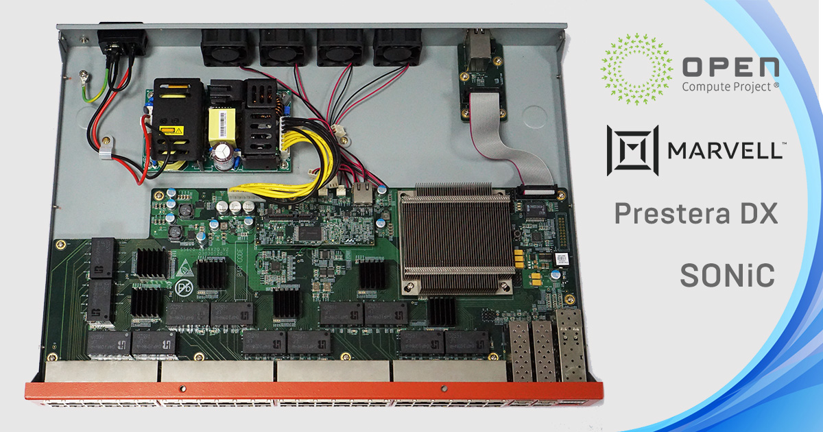
We've prepared a step-by-step guide for assembling and launching reference firmware with CPSS on the Marvell RD-AC3X-48G4X2XL-A board. This board serves for managed switches with up to 48 ports design and debugging. What makes it a perfect fit for an engineer? It has a Marvell Prestera DX 98DX3257 switch with a powerful Prestera SoC family on board. Besides, Prestera DX Ethernet switches enable 5G at the industry's lowest requirements for power and space.
As for CPSS, it is the basic software layer for Marvell Prestera hardware. CPSS stands for Core Prestera Software Suite. Open Compute Project uses CPSS as a part of the SONiC open network operating system. This OS extends data center functions in complex systems, such as intelligent data storage and machine learning.
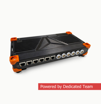
Reference platforms like the RD-AC3X-48G4X2XL-A are most valuable when you’re using them as a bridge between evaluation and a real product roadmap. We’ve seen this path firsthand in our Linux + CPSS for industrial managed L2 Ethernet switches case, where the goal was to bring managed switching features into rugged, deployable 8- and 16-port devices—covering everything from board bring-up with u-boot and Linux to SDK integration and L2 management functions (VLANs, STP/RSTP/MSTP, SNMP, IGMP, and more). The workflow below follows the same logic: get a reproducible Linux environment running on the reference hardware, validate the switch stack, and then build on top of it with your own management plane and product-specific integrations.
Contents
- Introduction
- Step 0: Create a working directory
- Step 1: Download the toolchain (compiler, etc.) to build the kernel and cpss-application
- Step 2: Download the Marvell assembly system with CPSS sources
- Step 3: Download instructions for assembling and using the Linux Marvell and CPSS image
- Step 4: Clone the Linux-Marvell kernel from Marvell Github and configure it
- Step 5: Configure the desktop environment
- Step 6: Build the kernel and the device tree
- Step 7: Assemble CPSS
- Step 8: Build the kernel modules to make CPSS work
- Step 9: Download the busybox 1.21.1
- Step 10: Fix the Makefile
- Step 11: Build the file system
- Step 12: Install and configure the TFTP server
- Step 13: Set up u-boot on the device
- Step 14: Ensure, that the CPSS application works on the device
Moreover, CPSS high-level API helps developers leverage features of Marvell Packet Processor without in-depth knowledge of Prestera chipset registers and tables.
CPSS locates in the user environment. It has several functions that require kernel-specific support:
- Interrupts: a dedicated kernel module for forwarding Packet Processor interrupts to the CPSS.
- To-and-fro CPU packet: another kernel module for forwarding packets between the PCIe interface to dedicated SDMA memory.
That API allows complete configuration of the Prestera-based switch.
Our board already has a u-boot. It is loaded into the device nand-memory on the vendor side.
Before following the steps in our guide, please, create an account on the Marvell portal.
Step 0: Create a working directory
mkdir /marvell && cd marvellBelow you’ll find all the components you need to download and unpack in the ~/marvell directory (/marvell). All the paths in the guide are relative to it.
Step 1: Download the toolchain (compiler, etc.) to build the kernel and cpss-application
1.1 Go to the Marvell portal and select Products in the top center.
1.2 Follow Tools→Marvell GNU Tools→MGCC-5→201511 on the left in the menu.
1.3 Select Toolkit in the window on the right and download the necessary toolchain. At the time of this guide preparation this is armv7 marvell linux gnueabihf hard 5.2.1 x86_64 20160301.tar.xz.
1.4 Unpack the archive to the working directory.
Step 2: Download the Marvell assembly system with CPSS sources
2.1 In the same Products section on the Marvell portal, select Switching→Software→CPSS-DXCH→4.2.2020.3 from the menu on the left.
2.2 Click on the window on the right side of Base SDK and download CPSS 4.2.2020.3 release – GIT Source.
2.3 Unpack the archive into the working directory.
Step 3: Download instructions for assembling and using the Linux Marvell and CPSS image
3.1 Again from the menu on the left, in the Products section, select Switching→Software→cpss→4.2.2020.3.
3.2 Click the User Guide in the window on the right and download PSDK PIPE 4.2.2020.3 Release – User Guide.
3.3 User Guide is a set of html-pages for browsers. To view it, unzip the archive and open the page in the root – PSDK_home.html.
Step 4: Clone the Linux-Marvell kernel from Marvell Github and configure it
4.1 git clone https://github.com/MarvellEmbeddedProcessors/linux-marvell.git
4.2 mv ./linux-marvell ./cpss_release_git_CPSS_4.2_2020_03_018/kernel
Please note that the kernel must be located near the sources of cpss. Its name must be kernel.
4.3 cd ./cpss_release_git_CPSS_4.2_2020_03_018/kernel
4.4 git checkout remotes/origin/linux-4.4.52-armada-17.10
4.5 export ARCH=arm && make mvebu_v7_lsp_defconfig
Next, enable RAM disk support in the kernel. There are two ways to do this:
– via make menuconfig
– or write the following code in your .config file:
CONFIG_BLK_DEV_RAM=y
CONFIG_BLK_DEV_RAM_COUNT=2 (maximum possible number of RAMs)
CONFIG_BLK_DEV_RAM_SIZE=524288 (the maximum size of a RAM disk in kb that the kernel can support; 524288 is 512 mb)
Step 5: Configure the desktop environment
Refer to the User Guide from Step 3 for the configuration process.
5.1 cd PSDK_PIPE_4.2.2020.3_UserGuide
5.2 Open PSDK_home.html.
5.3 CPSS User Guide on the left.
5.4 Building CPSS → Building CPSS in Linux → Installing the Development Environment — on the left.
5.5 Skip Tool Chain Installation, we have already installed it. Go to Configuring the Development Environment. There we make all further configurations.
Next steps (6-12) are taken in the ./cpss_release_git_CPSS_4.2_2020_03_018/cpss directory
Step 6: Build the kernel and the device tree
6.1 git checkout cpss_4.2
6.2 make ARCH=arm CROSS_COMPILE=$(pwd)/../../armv7-marvell-linux-gnueabihf-hard-5.2.1_x86_64_20160301/bin/arm-marvell-linux-gnueabihf- TARGET=armv7 FAMILY=DX DEBUG_INFO=Y kernel
Step 7: Assemble CPSS
make ARCH=arm CROSS_COMPILE=$(pwd)/../../armv7-marvell-linux-gnueabihf-hard-5.2.1_x86_64_20160301/bin/arm-marvell-linux-gnueabihf- TARGET=armv7 FAMILY=DX DEBUG_INFO=Y appDemo
Step 8: Build the kernel modules to make CPSS work
make ARCH=arm CROSS_COMPILE=$(pwd)/../../armv7-marvell-linux-gnueabihf-hard-5.2.1_x86_64_20160301/bin/arm-marvell-linux-gnueabihf- TARGET=armv7 FAMILY=DX DEBUG_INFO=Y modules
Marvell provides 3 kernel modules:
- mvIntDrv.ko — for processing interrupts from/for Packet Processor
- mvDmaDrv.ko — o for allocating the DMA memory that sends packets to/from the CPU
- mvMbusDrv.ko — for accessing internal resources when using Prestera's internal processor
Now, let’s assemble the file system:
Step 9: Download the busybox 1.21.1
mkdir busybox && wget -P busybox https://busybox.net/downloads/busybox-1.21.1.tar.bz2
Step 10: Fix the Makefile
Open the root Makefile in cpss_release_git_CPSS_4.2_2020_03_018/cpss
and replace the line:
tools/build/rootfs/crfs.sh $(BUILD_FOLDER)/rootfs $(CROSS_COMPILE) /nfs/pt/swdev/areas/readonly/swtools/devsources/root_fs/files/busybox/busybox-1.22.1.tar.bz2; </em>
to:
tools/build/rootfs/crfs.sh $(BUILD_FOLDER)/rootfs $(CROSS_COMPILE) $(MY_DIR)/busybox/busybox-1.21.1.tar.bz2; </em>
Step 11: Build the file system
Instead of storing on the device, the file system will be stored on a RAM disk. The RAM disk will be loaded into the device RAM. This is the most beneficial storage option, since the amount of memory used does not exceed 256 MB.
11.1 make ARCH=arm CROSS_COMPILE=$(pwd)/../../armv7-marvell-linux-gnueabihf-hard-5.2.1_x86_64_20160301/bin/arm-marvell-linux-gnueabihf- TARGET=armv7 FAMILY=DX DEBUG_INFO=Y rootfs
We have already built the CPSS and the module to work with it in steps 7 and 8. Now copy them into the file system:
11.2 cp compilation_root/cpss_4.2/armv7_DX/appDemo cpssEnabler/mainExtDrv/src/gtExtDrv/linuxNoKernelModule/drivers/mvDmaDrv.ko cpssEnabler/mainExtDrv/src/gtExtDrv/linuxNoKernelModule/drivers/mvIntDrv. ko cpssEnabler/mainExtDrv/src/gtExtDrv/linuxNoKernelModule/drivers/mvMbusDrv.ko compilation_root/cpss_4.2/armv7_DX/rootfs/home/user/
Compile a file system image that is suitable for u-boot. We do this with mke2fs and mkimage:
11.3 cd compilation_root/cpss_4.2/armv7_DX && mke2fs -L '' -N 0 -O ^64bit -d rootfs -t ext2 rootfs.ext2 256M && gzip rootfs.ext2 && mkimage -A arm -O linux -T ramdisk -C gzip -n "Build Root File System" -d rootfs.ext2.gz rootfs.ext2.gz.uboot && cd -
The kernel, device tree, and RAM disk of the file system will be booted to the device via TFTP. It is also possible to write them to the NAND-memory of the device after the end of the development and debugging cycle. But we will stop with TFTP. You will need a connection between the host machine and the device (Ethernet port on the back of the device) and a TFTP server on the host.
Step 12: Install and configure the TFTP server
12.1 sudo apt install -y tftpd-hpa
12.2 sudo systemctl enable tftpd-hpa && sudo systemctl restart tftpd-hpa
Copy the kernel, device tree, and RAM disk file system to /var/lib/tftpboot. /var/lib/tftpboot is the home directory for the TFTP server.
12.3 sudo cp ../kernel/arch/arm/boot/zImage ../kernel/arch/arm/boot/dts/armada-38x-interposer.dtb compilation_root/cpss_4.2/armv7_DX/rootfs.ext2.gz.uboot /var/lib/tftpboot
Step 13: Set up u-boot on the device
13.1 Plug the Ethernet cable into the MGMT port on the back of the unit – this is the TFTP connection.
13.2 Connect the RS232 (host) – RJ-45 (device) cable to the CONSOLE port – this is your console.
13.3 Start minicom to connect to the device console. Port settings: 115200 8N1.
13.4 Turn on the device. Immediately, the bootloader gives the message: "Hit any key to stop autoboot:". Press any key to enter the u-boot settings menu.
13.5 Perform the following commands one after another in the u-boot console:
- setenv bootcmd "run bootcmd_ram ;"
- setenv bootcmd_ram "run tftp_ramdisk; setenv bootargs $console root=/dev/ram0 rw; tftp $loadaddr $image_name; tftp $fdtaddr $fdtfile; bootz $loadaddr ${ramdisk_addr}:${initrd_size} $fdtaddr ;"
- setenv tftp_ramdisk "tftp $ramdisk_addr $ramdisk_name; setenv initrd_size ${filesize}"
- setenv ramdisk_addr "0x05200000".
- setenv ramdisk_name "rootfs.ext2.gz.uboot"
- setenv console "ttyS0,115200"
- setenv loadaddr "0x02000000"
- setenv image_name "zImage"
- setenv fdtaddr "0x1000000"
- setenv fdtfile "armada-38x-interposer.dtb"
- saveenv
13.6 Boot! :-)
- boot
Step 14: Ensure, that the CPSS application works on the device
Load the kernel modules:
14.1 cd /home/user && insmod mvDmaDrv.ko && insmod mvIntDrv.ko && insmod mvMbusDrv.ko
Run the CPSS application:
14.2 ./appDemo
This takes you to the console of the CPSS application. In the console we can configure the Ethernet ports on the switch and the entire Prestera system. To check the application workability, we will connect one of the switch front panel Ethernet ports (any port) to a free port on the host machine. After linking them together, ping the host machine with the following commands:
14.3: autoInitSystem — initialize the Prestera system – this command must be executed after each reboot of the switch.
14.4: Next, run the following commands one by one
- configure
- mac address 00:00:00:00:11:22
- interface ethernet 0/35
- ip address <IP in the same subnet as the host> <mask of that subnet
- force link up
- end
- traffic
- protocol enable arp
- protocol enable ping
- ping <IP of the host you want to ping
If the ping is successful, you will see the following:
<Console(traffic)# ping 192.168.15.3>
<Pinging 192.168.15.3 using src mac: 00:00:00:00:11:22 src ip:192.168.15.10>
<Ping to ip 192.168.15.3 successful.>
Congratulations! You've just configured Linux and CPSS on the Marvell RD-AC3X-48G4X2XL-A board with the Prestera DX Ethernet switch!
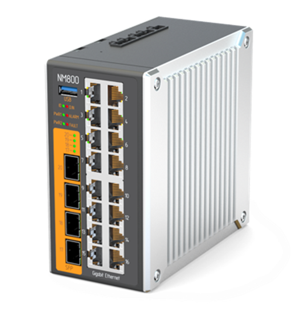
Picture: Industrial Ethernet switch 1Gb/10Gbps based on OS Linux, developed on the same family of network chips as the debugger (48 downlink ports + 4 uplink ports, operating range: -20–70°C)
This guide is helpful for both theory and practice. You can explore the capabilities of the Marvell Prestera switch (L2, CAPWAP, CNC, DCE, PHY, EEE, IP, NAT, etc.) together with the Lua CLI or develop your own high-level Marvell Prestera-based application for network equipment.
A full description of the CPSS commands you can find in the User guide from Step 3 in the Lua CLI User Guide.