How to Design an AI Telematics Unit for Fleets with Cameras, GNSS, CAN and Cellular in One Edge Box
Fleet telematics has shifted from simple tracking devices to fully integrated edge systems that must sense, compute, and communicate in real time. A modern AI telematics unit is expected to process video streams, read vehicle data, determine precise location, detect events, and transmit data over unreliable cellular networks, all within a compact and thermally constrained enclosure. The difficulty is not integrating these subsystems individually, but ensuring that they operate together without introducing latency bottlenecks, data misalignment, or system instability.
The system is fundamentally multi-domain. Video pipelines operate at high bandwidth and require continuous compute, CAN interfaces deliver low-bandwidth but timing-sensitive signals, GNSS provides low-rate but high-precision positioning, and cellular introduces non-deterministic latency and bandwidth. Designing such a system requires thinking in terms of data flow, scheduling, and worst-case conditions rather than nominal performance.
System Architecture: Converging Heterogeneous Pipelines
An AI telematics unit is best understood as a set of parallel pipelines that converge into a single compute and communication node. Each pipeline has its own timing, bandwidth, and processing requirements, and the architecture must ensure that no pipeline blocks another.
At the hardware level, the system typically includes a central SoC with CPU cores and an AI accelerator, one or more camera interfaces using MIPI CSI or serialized links, a GNSS receiver connected via UART or SPI, CAN transceivers for vehicle communication, and a cellular modem connected via PCIe or USB. Local storage, usually eMMC or NVMe, is used for buffering and logging.
The critical architectural constraint is that these subsystems are not independent. They share memory bandwidth, CPU time, and I/O paths. A camera pipeline generating hundreds of megabytes per second can saturate memory and delay CAN processing if not properly isolated. Similarly, a burst of cellular transmission can consume CPU cycles and interfere with real-time tasks.
To prevent this, the architecture must enforce separation at multiple levels. CPU cores are typically partitioned so that real-time tasks such as CAN processing run on isolated cores, while AI inference and communication tasks run on separate cores. Memory bandwidth must be managed through prioritization mechanisms, ensuring that time-critical data paths are not delayed by bulk transfers.
Camera Pipeline: Data Rates, Inference and Backpressure
The camera subsystem is the dominant source of data in the system. A single 1080p stream at 30 frames per second produces raw data rates on the order of 1 to 1.5 Gbps before compression. Even when compressed, multiple streams can quickly saturate internal buses.
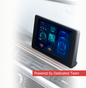
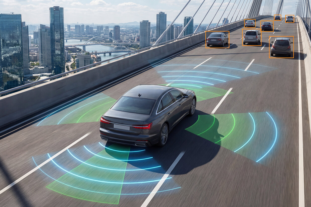
The pipeline begins with sensor capture, followed by image signal processing, which may be handled by dedicated hardware. Frames are then either encoded for storage or passed to an inference engine for analysis. In fleet applications, inference tasks include driver monitoring, object detection, and incident recognition.
The key challenge is maintaining throughput under worst-case conditions. If inference cannot keep up with incoming frames, buffers begin to fill, leading to backpressure. Eventually, frames must be dropped or latency increases beyond acceptable limits. This is particularly problematic in safety-related applications such as driver monitoring, where missed frames can lead to missed events.
To manage this, systems often implement frame skipping or adaptive processing. For example, inference may run at a lower frame rate than capture, or resolution may be reduced dynamically under load. Hardware accelerators are essential to maintain performance while keeping power consumption within limits.
GNSS: Low Bandwidth, High Impact on System Integrity
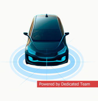
GNSS is often treated as a secondary subsystem due to its low data rate, but it plays a critical role in event correlation and system integrity. Position data is typically updated at 1 to 10 Hz, which is negligible compared to video data rates, but timing accuracy is essential.
GNSS provides a global time reference that can be used to synchronize data across subsystems. Without proper synchronization, correlating events becomes unreliable. For example, associating a harsh braking event with the corresponding video frame requires precise alignment between CAN timestamps, GNSS time, and camera capture time.
In real-world conditions, GNSS signals are degraded by urban canyons, tunnels, and multipath effects. Errors can reach several meters, and signal loss can last for extended periods. To mitigate this, systems often combine GNSS with inertial sensors or use dead reckoning. However, this introduces additional complexity and error accumulation over time.
The system must handle GNSS outages gracefully, maintaining relative positioning and time continuity until a reliable signal is restored.
CAN Integration: Deterministic Data in a Non-Deterministic System
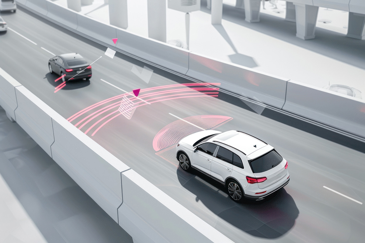
CAN provides access to vehicle data such as speed, braking, engine status, and driver inputs. Unlike video or GNSS, CAN data is event-driven and requires deterministic handling. Delays in processing CAN messages can lead to incorrect interpretation of vehicle behavior.
CAN operates at relatively low bandwidth, typically between 125 kbps and 1 Mbps, but the timing of messages is critical. Messages may arrive at intervals of a few milliseconds, and missing or delaying them can break higher-level logic.
The system must capture CAN frames with minimal latency, decode them using DBC definitions, and integrate them into the overall data pipeline. This requires careful scheduling to ensure that CAN processing is not delayed by high-load tasks such as video processing or data transmission.
In practice, CAN handling is often assigned to a dedicated core or handled by a real-time operating system running alongside a general-purpose OS. This separation ensures that deterministic behavior is maintained even under high system load.
Cellular Connectivity: Designing for Variability
Cellular connectivity introduces the most uncertainty into the system. Unlike internal data paths, which are predictable, cellular bandwidth and latency vary depending on network conditions, coverage, and load.
Uplink bandwidth can range from a few hundred kilobits per second to tens of megabits per second. Latency can vary from tens to hundreds of milliseconds, and connectivity may be intermittent in remote areas.
The system must be designed to operate correctly under worst-case conditions, not average ones. This requires buffering, prioritization, and adaptive transmission strategies. Critical events, such as collision detection, must be transmitted immediately, while less important data can be delayed or compressed.
A typical strategy includes:
- event-driven transmission for critical data
- batch upload for non-critical data
- local buffering during connectivity loss
- adaptive bitrate and compression
These mechanisms ensure that the system remains functional even when network conditions degrade.
Data Synchronization: The Hidden Complexity
One of the most challenging aspects of telematics design is synchronizing data from multiple sources. Each subsystem operates on its own clock and update rate, and aligning these streams is non-trivial.
Cameras may operate at 30 frames per second, CAN messages may arrive every few milliseconds, and GNSS updates may occur once per second. Cellular transmission adds additional delays.
To create a coherent timeline, the system must timestamp data at the source and align it during processing. This requires a consistent time base, often derived from GNSS or a synchronized internal clock.
Even small timing errors can lead to incorrect conclusions. For example, if a braking event is associated with the wrong video frame, analysis becomes unreliable. This is particularly important in applications such as incident reconstruction or driver behavior analysis.
Compute Allocation and Scheduling
The compute platform must handle multiple workloads simultaneously. CPUs handle control logic, communication, and some data processing, while GPUs or NPUs handle AI inference.
Workloads must be distributed to avoid contention. If video processing monopolizes CPU resources, CAN handling may be delayed. If inference tasks are not properly scheduled, latency may increase.
Parallel processing is essential. Pipelines must run concurrently, with minimal blocking. This requires careful design of thread scheduling, memory access, and inter-process communication.
In many systems, containerization or virtualization is used to isolate workloads. This allows different components to run independently while sharing hardware resources.
Power and Thermal Constraints
Telematics units operate in harsh environments with limited cooling. Power consumption must be controlled to prevent overheating and ensure reliability.
AI inference is a major contributor to power consumption. Continuous video processing can significantly increase thermal load, leading to throttling. When thermal limits are reached, performance is reduced, which can cause missed deadlines or degraded functionality.
Thermal design must consider worst-case scenarios, including high ambient temperatures and sustained load. This may require heat sinks, thermal spreading, and dynamic power management.
Storage and Data Retention
Local storage is required to buffer data and store events. Video clips, logs, and metadata must be stored reliably until they can be transmitted.
Storage systems must support high write rates and ensure data integrity. Flash memory is commonly used, but endurance must be managed through wear leveling and error correction.
Buffering strategies determine how long data can be retained during connectivity loss. This affects system behavior in remote areas or during network outages.
Failure Scenarios and System Behavior
Real-world systems must handle a wide range of failure scenarios. Camera pipelines may overload, leading to dropped frames. GNSS signals may be lost, reducing positioning accuracy. CAN messages may be delayed or corrupted. Cellular connectivity may be unavailable.
The system must detect these conditions and adapt. For example, if connectivity is lost, data must be buffered locally. If GNSS is unavailable, the system must rely on alternative positioning methods.
Failure handling must be designed as part of the system, not added later. This includes monitoring, error detection, and recovery mechanisms.
Deployment Patterns in Fleet Systems
In production, telematics units are deployed across diverse vehicle types and operating conditions. The architecture must be scalable and adaptable.
A common pattern is a single edge box connected to multiple sensors, with centralized processing and cloud integration. Software updates allow continuous improvement without hardware changes.
Validation must include worst-case scenarios, including maximum load, poor connectivity, and adverse environmental conditions.
Quick Overview
AI telematics units combine cameras, GNSS, CAN, and cellular connectivity into a single edge device for fleet applications.
Key Applications
Fleet monitoring, driver behavior analysis, incident detection
Benefits
Real-time insights, reduced bandwidth usage, scalable deployment
Challenges
System integration, latency management, power and thermal constraints
Outlook
Growing adoption of edge AI with increasing integration of sensing and connectivity technologies
Related Terms
edge computing, telematics, CAN bus, GNSS, cellular networks
Our Case Studies