How to Build a Complementary Short-Range Sensing Stack with UWB, Radar and Vision
Short-range sensing inside a vehicle is no longer a single-sensor problem. Modern use cases such as child presence detection, driver monitoring, gesture control, interior mapping, and secure access require reliable detection under conditions that are inherently unstable. Lighting changes, occlusions, reflections, and RF interference all occur simultaneously in a confined environment. Any sensing system that relies on a single modality is more likely to degrade or fail in edge cases, and in automotive systems edge cases define system reliability.
UWB, 60 GHz mmWave radar and vision systems are increasingly deployed together not because they overlap, but because they fail differently. The engineering task is to build a sensing stack where these failures are uncorrelated and can be compensated through fusion. This requires detailed understanding of signal behavior, timing constraints, and system architecture, not just sensor specifications.
Physical Principles and Why They Matter for System Design
Each sensing modality is built on a fundamentally different physical principle, and these differences directly determine where each sensor works and where it fails.
UWB relies on precise time-of-flight measurement of short radio pulses spread over a wide bandwidth. This allows distance estimation with high temporal resolution and relatively good robustness to multipath compared to narrowband systems. However, UWB does not provide semantic understanding or dense spatial mapping. It answers the question “where is the device” but not “what is the object.”
60 GHz mmWave radar uses frequency-modulated continuous wave signaling and analyzes reflected signals to extract range, velocity, and motion characteristics. It is sensitive to micro-movements, including respiration, and operates independently of lighting conditions. However, radar returns are inherently ambiguous. Reflections from multiple surfaces create ghost targets, and object classification is limited without additional context.
Vision systems rely on image capture and processing, typically combined with neural networks. They provide dense spatial information and semantic classification, making them essential for understanding occupancy, posture, and object identity. At the same time, they are highly dependent on environmental conditions. Low light, direct sunlight, occlusion, and reflections can all degrade performance.
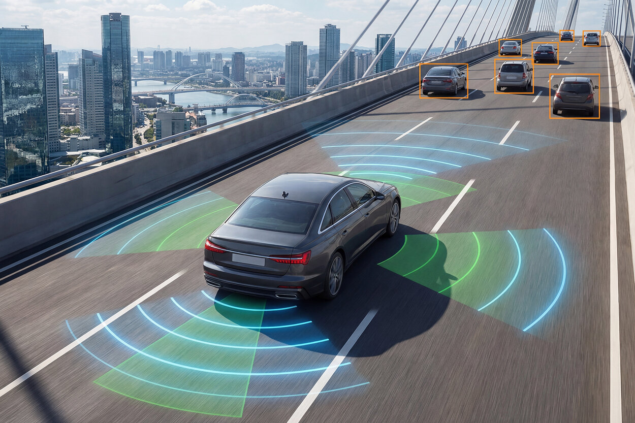
These differences define the complementary nature of the sensing stack. UWB provides absolute spatial reference when a device is present, radar provides motion detection even when objects are hidden, and vision provides classification when visibility is sufficient. The system must be designed so that failure modes do not align across sensors.
UWB in Automotive Systems: Capabilities and Constraints
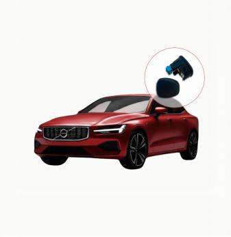
UWB is often introduced into vehicles through digital key systems, but its role in sensing is broader. By measuring round-trip time-of-flight, UWB can determine distance between anchors and tags with accuracy typically in the range of 10 to 30 centimeters under controlled conditions. In practice, accuracy degrades due to non-line-of-sight propagation, antenna placement, and interference.
Inside a vehicle, anchors are distributed across structural elements such as pillars, doors, and the roof. This allows triangulation of tag position. However, the human body introduces attenuation, often exceeding several decibels, and metallic components create reflections that distort measurements. While UWB is more robust to multipath than narrowband systems, it is not immune to errors caused by indirect paths.
A key limitation is that UWB requires a cooperative device. If the system relies on a smartphone or tag, it cannot detect occupants who do not carry such a device. This makes UWB unsuitable as a standalone sensing modality for safety-related functions.
Another constraint is update rate. UWB systems are not designed for high-frequency continuous tracking in the same way as radar. Measurement cycles, synchronization, and regulatory constraints limit how frequently ranging updates can be performed. This introduces latency that must be considered in fusion.
Despite these limitations, UWB provides a stable spatial reference that is difficult to obtain from other sensors. When available, it can significantly reduce ambiguity in multi-sensor fusion.
60 GHz Radar: Motion Sensitivity and Multipath Challenges
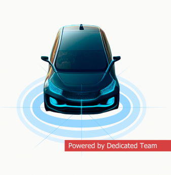
Radar operating at 60 GHz offers a unique capability: detection of motion independent of visibility. By analyzing phase shifts and frequency changes in reflected signals, radar can detect not only movement but also micro-movements such as breathing. This makes it particularly valuable for occupant detection and child presence monitoring.
The short wavelength at 60 GHz allows for relatively compact antennas and higher spatial resolution compared to lower-frequency radar systems. However, the interior of a vehicle creates a highly reflective environment. Signals bounce off seats, windows, and structural elements, producing multiple reflections that appear as separate targets.
Signal processing algorithms attempt to filter these reflections, but complete elimination is not possible. As a result, radar systems often produce ambiguous outputs. A stationary object may appear as noise, while reflections may be misinterpreted as movement.
Another constraint is field of view. Radar modules must be positioned carefully to cover the intended area without excessive overlap or blind spots. In practice, multiple radar modules may be required to cover the entire cabin, increasing system complexity and potential interference between modules.
Interference between radar units becomes a real issue when multiple transmitters operate in similar frequency ranges. Time multiplexing or frequency separation must be implemented to avoid mutual interference, which introduces additional coordination requirements.
Vision Systems: High Information Density with Environmental Dependency
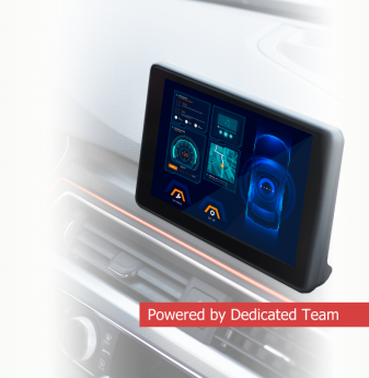
Vision systems provide the richest data among the three modalities. A single camera frame contains dense spatial information that can be processed to identify objects, classify occupants, and interpret behavior. Modern systems rely heavily on neural networks for tasks such as face detection, pose estimation, and gesture recognition.
However, this richness comes at a cost. Vision systems are highly sensitive to environmental conditions. Direct sunlight can saturate sensors, while low light conditions reduce signal-to-noise ratio. Shadows and reflections introduce additional complexity. Infrared cameras mitigate some of these issues but add cost and integration challenges.
Processing requirements are significant. Running neural networks for real-time inference requires dedicated accelerators or high-performance processors. This increases power consumption and introduces thermal constraints, particularly in enclosed automotive environments.
Latency is another critical factor. Image capture, preprocessing, inference, and post-processing all contribute to delay. Depending on system design, vision latency can range from tens to hundreds of milliseconds. This must be accounted for in fusion, especially when combined with faster sensors such as radar.
Complementarity in Practice: How the Stack Works Together
The goal of combining UWB, radar, and vision is not redundancy but complementarity. Each sensor provides information that others cannot, and the system must be designed to exploit these differences.
In a typical occupant detection scenario, radar continuously monitors motion and detects the presence of a person even when hidden. Vision provides classification and confirms whether the detected object is a human, as well as posture and location. UWB, if a device is present, provides precise localization and identity linkage.
This combination allows the system to handle edge cases. If a person is covered by a blanket, vision may fail, but radar detects breathing. If radar produces ambiguous reflections, vision clarifies the situation. If both are uncertain, UWB provides additional context when available.
The system must assign confidence levels to each sensor input and adjust decision-making dynamically. This requires careful design of fusion algorithms and thresholds.
Fusion Architecture: From Signals to Decisions
Sensor fusion is not a single algorithm but a pipeline that transforms heterogeneous data into a coherent representation.
The first stage is sensor-specific preprocessing. Radar data is filtered to remove noise and extract targets. Vision data is processed through neural networks to extract features such as bounding boxes and classifications. UWB data is converted into distance or position estimates.
The second stage is alignment. Data from different sensors must be synchronized in time and mapped to a common coordinate system. This is non-trivial because sensors operate at different update rates and have different latencies.
The third stage is fusion. Common approaches include probabilistic methods such as Bayesian inference or filtering techniques such as Kalman filters. These methods combine measurements while accounting for uncertainty.
Finally, decision logic interprets fused data to produce system outputs. This may involve thresholding, state machines, or higher-level reasoning.
Fusion must handle conflicting data. For example, radar may detect motion while vision sees no object. The system must determine whether this is a false positive, an occlusion, or a sensor failure.
Latency and Synchronization Constraints
Each sensor contributes differently to system latency. Radar typically has low latency but requires filtering over time. UWB has moderate latency due to ranging cycles. Vision has the highest latency due to processing requirements.
Synchronization errors between sensors can lead to incorrect fusion. For example, if radar detects movement slightly before vision confirms it, misalignment can cause incorrect interpretation.
Time synchronization mechanisms must ensure that sensor data is aligned within tight bounds, often on the order of milliseconds. This requires hardware support and careful software design.
RF and System-Level Interference
Although UWB and 60 GHz mmWave radar operate in different frequency bands, system-level interference can still occur. Shared power supplies, PCB coupling, and electromagnetic emissions can introduce noise that affects sensor performance.
Antenna placement must consider both coverage and isolation. UWB antennas require distribution for triangulation, while radar antennas require clear fields of view. Poor placement can degrade both systems simultaneously.
In addition, multiple radar modules can interfere with each other if not properly coordinated. This requires scheduling or frequency planning, adding complexity to system design.
Hardware Integration and Packaging Constraints
Integrating multiple sensors into a vehicle is constrained by space, cost, and design requirements. Cameras require unobstructed optical paths, radar modules require specific mounting positions, and UWB anchors must be distributed for coverage.
Power consumption is cumulative. Adding sensors increases load, and thermal management becomes critical. Enclosed spaces and limited airflow exacerbate thermal issues.
Cost is also a factor. While adding sensors improves reliability, it increases bill of materials and integration complexity. System designers must balance performance and cost.
Failure Modes and Real-World Behavior
Real systems must handle a wide range of failure scenarios.
Vision systems may fail due to glare or darkness. Radar may produce false positives due to reflections. UWB may lose signal due to obstruction or lack of a cooperative device.
The key is not eliminating failures but detecting them and adapting. The system must recognize when a sensor is unreliable and adjust fusion accordingly.
Conflicting data is common. Fusion algorithms must assign confidence levels and resolve inconsistencies without introducing instability.
Deployment Patterns in Production Systems
In production vehicles, sensors are distributed to maximize coverage and minimize interference.
Typical configurations include:
- cameras in the cabin for vision-based detection
- radar modules in roof or seat structures for motion detection
- UWB anchors distributed across the vehicle for localization
Data is processed in a central compute unit, where fusion algorithms run. This allows updates and improvements through software without changing hardware.
System validation must include worst-case scenarios, including occlusion, interference, and extreme environmental conditions.
Quick Overview
Combining UWB, 60 GHz mmWave radar , and vision enables a complementary short-range sensing stack for automotive applications.
Key Applications
Occupant detection, child presence monitoring, gesture control, secure access
Benefits
Improved reliability, reduced false detections, robust operation across conditions
Challenges
Sensor fusion complexity, hardware integration, latency management
Outlook
Increasing adoption of multi-sensor systems with more advanced fusion algorithms
Related Terms
UWB, FMCW radar, computer vision, sensor fusion, automotive sensing
Our Case Studies