P4 Network Programming Language: P4-supported Hardware, and SONiC-P4 Configuration
We launch a series of articles on the relatively new programming language P4 and what it is all about. In the first part, we will find out its general description and purpose. We also believe that practice makes perfect, so we'll look at coding examples and hardware with P4 support. We saved the best for last: a step-by-step guide on how to configure Sonic-P4. Let's go!
The P4 programming language enables developers to define how network packets are processed, making it a powerful tool for building customised network functions. For those new to the P4 network programming language, a P4 language tutorial can provide step-by-step guidance on writing P4 programs, understanding match-action tables, and deploying them on programmable switches. Mastering P4 allows network engineers to implement advanced data plane features, optimise network performance, and adapt to evolving network requirements.
Let's discuss a bit of theory. P4 language or Programming Protocol-Independent Packet Processors is an open-source, domain-specific network programming language for specifying the processing of packets by data plane devices like routers, switches, NICs, etc.
Originally, P4 served for programming of the sending the data plane packets of network switches, but eventually, it covered other network devices like routers, software & hardware switches, network interface cards.
The ability of a developer to make a custom description of headers with the field names and choose any desired protocol makes the language protocol independent.
Most network devices implement both the control plane and the data plane. P4 describes packet processing only in the context of the data plane, and more specifically, defines the functionality of the device's data plane.
P4 programs can also partially define the communication interface between the control plane and the data plane, but they cannot describe the control level functions of the device. Let us show this with a simple example:
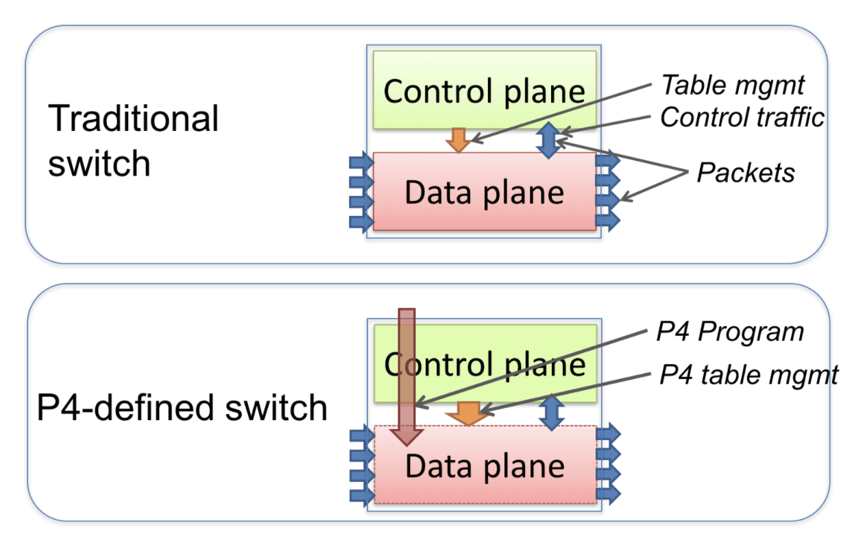
Standard and P4-defined switches
The diagram shows the difference between a standard switch and a P4-defined switch. In the standard device, the manufacturer defines the functionality of the data plane. The control plane controls the data plane, viz:
- manages the records in the tables;
- configures specialized objects, such as registers;
- processes control packets.
Now let's take a look at the two main differences between the P4-defined switch:
- The functionality of the data plane is not initially defined, i.e. it can be described by the programmer. The configuration of the data plane according to the code takes place during the initialization of the device. We have marked this with the red arrow.
- The control plane and data plane interact through the same channels as in the standard switch, but the set of tables and other objects in the data plane is no longer fixed. The P4 program determines it. The P4 compiler generates an API that uses the control plane to communicate with the data plane.
P4 abstractions
We move on to the P4 abstractions and their brief description:
Headers describe the format or set of fields and their sizes for each header in a packet.
Parsers describe the allowed header sequences in received packets, header identification rules and fields for extraction from packets. Essentially, the main task of parsers is to identify and parse the header correctly.
P4 tables combine keys, actions, and the relationships between them. They generalize traditional switching tables and help implement routing tables, access control lists, and the creation of complex custom tables. The only thing that limits the number of tables is the programmer's needs. Entries in tables are sequential unless there is no abstract table that consists of several custom tables.
Actions are code fragments that describe the rules for handling the packet header fields and metadata.
Match-Action modules are components of tables for performing the following:
- Creation of a search key from package fields or calculated metadata.
- Searching in the table to match the created key to the desired action.
- Performing the retrieved action.
A control flow is an imperative program that describes how packets are processed on the device, including the sequence of calls to the Match-Action modules.
P4 abstract forwarding model. Source: researchgate.net
External objects are architecture-dependent constructs controlled by P4 programs using well-defined APIs. It is worth mentioning that we cannot adjust the internal behaviour of external objects. Here are several examples: checksum, counters, registers, etc.
User metadata are data structures that are associated with each package. The user defines them.
Internal metadata are the data structures that are associated with each package. Internal metadata is defined by the architecture.
P4 Programming Examples
Device manufacturers usually provide the hardware or software implementation environment, the architecture and the P4 compiler.
The user defines a program in P4 for a specific architecture. The compiler generates a data plane configuration that implements forwarding logic and an API to control the state of data plane objects from the control plane.
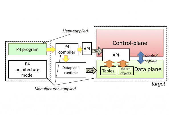
The diagram shows an example of device programming using P4
The domain-specific P4 language can be implemented on various devices, including programmable network interface cards, FPGAs, software switches and hardware ASICs. Nevertheless, P4 software developers are limited in designs based on these platforms.
Given the fixed cost of table lookup operations and interactions with external objects, both parsers and control elements perform a constant number of procedures for each byte of the incoming packet. Parsers may contain loops, but the packet itself provides a constraint on the total parser execution.
Thus, the computational complexity of the P4 program is linear in the total size of all headers. It never depends on the size of the state that has accumulated during data processing, such as the number of threads or the total number of packets processed. In this case, it seems that fast packet processing is guaranteed, but this is not enough. There are some minor issues.
Let's take a look at P4 through some real-life cases. Below you may see the header, parser, and table for the Very Simple Switch model.
#include <core.p4>
#include <v1model.p4>
const bit<16> TYPE_IPV4 = 0x800;
/*******************************************
********** H E A D E R S ******************
*******************************************/
typedef bit<9> egressSpec_t;
typedef bit<48> macAddr_t;
typedef bit<32> ip4Addr_t;
header ethernet_t {
macAddr_t dstAddr;
macAddr_t srcAddr;
bit<16> etherType;
}
header ipv4_t {
bit<4> version;
bit<4> ihl;
bit<8> diffserv;
bit<16> totalLen;
bit<16> identification;
bit<3> flags;
bit<13> fragOffset;
bit<8> ttl;
bit<8> protocol;
bit<16> hdrChecksum;
ip4Addr_t srcAddr;
ip4Addr_t dstAddr;
}
/****************************************
********** P A R S E R ******************
*****************************************/
parser MyParser(packet_in packet,
out headers hdr,
inout metadata meta,
inout standard_metadata_t standard_metadata) {
state start {
transition parse_ethernet;
}
state parse_ethernet {
packet.extract(hdr.ethernet);
transition select(hdr.ethernet.etherType) {
TYPE_IPV4: parse_ipv4;
default: accept;
}
}
state parse_ipv4 {
packet.extract(hdr.ipv4);
transition accept;
}
}
action drop() {
mark_to_drop(standard_metadata);
}
action ipv4_forward(macAddr_t dstAddr, egressSpec_t port) {
standard_metadata.egress_spec = port;
hdr.ethernet.srcAddr = hdr.ethernet.dstAddr;
hdr.ethernet.dstAddr = dstAddr;
hdr.ipv4.ttl = hdr.ipv4.ttl - 1;
}
table ipv4_lpm {
key = {
hdr.ipv4.dstAddr: lpm;
}
actions = {
ipv4_forward;
drop;
NoAction;
}
size = 1024;
default_action = drop();
}
apply {
if (hdr.ipv4.isValid()) {
ipv4_lpm.apply();
}
}
Once we have enjoyed the headers and parsers, let's try to understand why P4 is so good and whether it is good at all.
P4 Advantages
P4 outperforms today's packet processing systems in the following points:
- Flexibility: P4 helps to represent packet forwarding policies as programs, unlike traditional switches that give users fixed-function forwarding mechanisms.
- Expressiveness: With P4, it is easy to represent complex hardware-independent packet processing algorithms. You only need to use general-purpose operations and table lookups. If we have enough resources, such programs are transferable between target hardware that implements the corresponding architectures.
- Resource mapping and management: P4 programs abstractly describe storage resources, such as an IPv4 source address. Compilers correlate fields to available hardware resources defined by the user and manage low-level elements.
- Software engineering: type checking, information hiding and software reuse.
- Component libraries: vendors' component libraries can wrap hardware-dependent functions into portable high-level P4 samples.
- Decoupling hardware and software evolution: device manufacturers can use abstract architectures to clearly separate low-level architecture elements from high-level processing.
- Debugging: manufacturers provide software architecture models for easy development and debugging of P4 programs.
Flexibility, simplicity, efficiency — sounds good, but do we have enough hardware that supports P4? Let's move on.
P4-Supported Hardware
P4 is a relatively new programming language, so hardware support is not robust enough yet. Below we list the products on which you can implement the full P4 language specification.
Barefoot Tofino 2 chips
Engineers at Barefoot Networks created a P4 language and ASIC type chipset that does not use a proprietary SDK such as Broadcom or Cavium.
Its high-speed channels and higher bandwidth exponentially scale the performance. Intel's Tofino 2 architecture also gives more resources to handle heavy workloads in distributed applications, virtual machine scaling, AI, and serverless deployments.
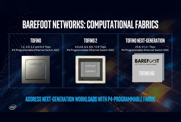
Barefoot Tofino 2 + Tofino products comparison
Netronome Agilio SmartNIC
SmartNIC products are standard PCIe network adapters with links that offload data plane functions to the NIC instead of helping applications or the core spend a lot of CPU resources on it. These products are not just switches or NICs. They don't have a default feature set available.
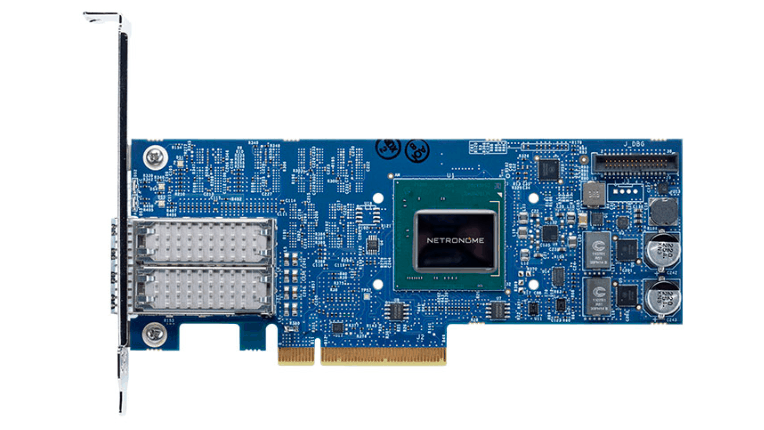
Netronome Agilio CX
Xilinx Alveo
Xilinx devices with P4 support are FPGA-based smart cards out of the Alveo product portfolio. Earlier versions of Alveo cards feature Xilinx Zynq UltraScale + FPGA circuits, while brand-new versions include the dedicated Xilinx UltraScale+ FPGA, which is only found in the Alveo line.
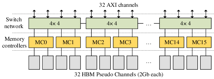
The HBM subsystem of Xilinx Alveo U280. Source: researchgate.net
The Alveo U25 card is available with two 10/25 GbE network interfaces, and all later versions have one or two 100 GbE interfaces.
Xilinx has its target FPGA platform for defining packet processing in the data plane — SDNet. From a P4 perspective, the SDNet environment offers several basic architecture models that P4 programmers can use. These architectures include XilinxSwitch, XilinxStreamSwitch, and XilinxEngineOnly.
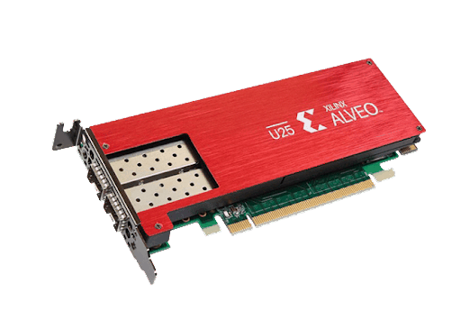
Xilinx Alveo U25
SONiC-P4 Software Switch
What is SONiC-P4?
SONiC-P4 is an ASIC-based software switch that emulates P4 and uses sai_bm.p4 to program the ASIC switch. It launches the SONiC network stack. The current version of SONiC-P4 was a simple docker image. SONiC-P4 runs wherever the docker does — on bare metal Linux / Windows machines, inside a virtual machine or in a cloud environment.
How to use SONiC-P4?
Let's demonstrate the use of the SONiC-P4 software switch:
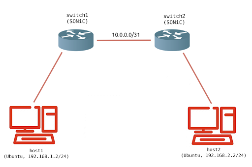
Test bench topology for the SONiC-P4 switch
Switch1 and switch2 are two SONiC-P4 switches in two different BGP AS that communicate with each other. Switch1 declares 192.168.1.0/24, switch2 declares 192.168.2.0/24.
- Download the necessary files on the Ubuntu server. Unzip the file and go to the sonic/ directory.
- To install docker and open-vswitch, launch the ./install_docker_ovs.sh.
- To download the SONiC-P4 image, do launch the ./load_image.sh.
- Launch ./start.sh to set up the bench. If everything is OK, four dockers will appear.
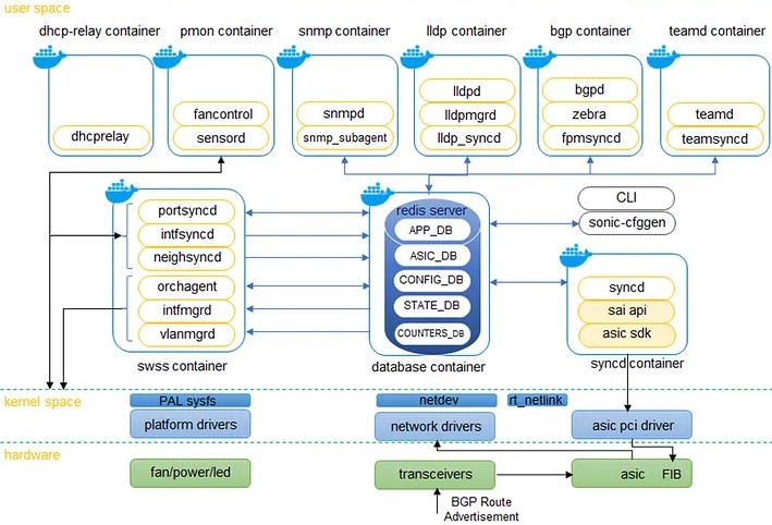
SONiC system blocks/docker containers. Source: medium.com
| CONTAINER ID | IMAGE | COMMAND | CREATED | STATUS | PORTS NAMES |
| db924306352f | ubuntu:14.04 | "/bin/bash" | 2 minutes ago | Up 2 minutes | host2 |
| ae5e987dee8c | ubuntu:14.04 | "/bin/bash" | 2 minutes ago | Up 2 minutes | host1 |
| aed19d76cd3a | docker-sonic-p4:latest | "/bin/bash" | 2 minutes ago | Up 2 minutes | switch2 |
| 680f95a83512 | docker-sonic-p4:latest | "/bin/bash" | 2 minutes ago | Up 2 minutes | switch1 |
- Wait a minute for it to load and run ./test.sh, which pings host2 from host1.
lgh@acs-p4:~/sonic$ ./test.sh
PING 192.168.2.2 (192.168.2.2) 56(84) bytes of data.
64 bytes from 192.168.2.2: icmp_seq=1 ttl=62 time=9.81 ms
64 bytes from 192.168.2.2: icmp_seq=2 ttl=62 time=14.9 ms
64 bytes from 192.168.2.2: icmp_seq=3 ttl=62 time=8.42 ms
64 bytes from 192.168.2.2: icmp_seq=4 ttl=62 time=14.7 ms
- Check BGP on switch1.
lgh@acs-p4:~/sonic$ docker exec -it switch1 bash
root@switch1:/# vtysh -c "show ip bgp sum"
BGP router identifier 192.168.1.1, local AS number 10001
RIB entries 3, using 336 bytes of memory
Peers 1, using 4568 bytes of memory
- Run ./stop.sh to clean up.
Topology configuration in start.sh
To configure the topology in start.sh we run four docker containers. As an example, let's take the command for switch1:
sudo docker run --net=none --privileged --entrypoint /bin/bash
--name switch1 -it -d -v $PWD/switch1:/sonic docker-sonic-p4:latest
We specify --net = none so that the Docker engine does not add its docker0 interface, which could interfere with the topology under test. The --privileged allows each container to configure its own interfaces. -v $ PWD / switch1: / sonic mounts the configuration folder to the switch containers.
Then we create three links. As an example, take the link between switch1 and switch2. The following commands connect the interface eth1 switch1 to the interface eth1 switch2:
sudo ovs-vsctl add-br switch1_switch2
sudo ovs-docker add-port switch1_switch2 eth1 switch1
sudo ovs-docker add-port switch1_switch2 eth1 switch2
Then we configure the interface IP address and default routes on host1 and host2. Example for host1:
sudo docker exec -d host1 ifconfig eth1 192.168.1.2/24 mtu 1400
sudo docker exec -d host1 ip route replace default via 192.168.1.1
Finally, we call the startup script for switch1 and switch2:
sudo docker exec -d switch1 sh /sonic/scripts/startup.sh
sudo docker exec -d switch2 sh /sonic/scripts/startup.sh
SONiC-P4 configuration
In start.sh we’ve installed the configuration folder in the switch container in /sonic. The most important configurations are in /sonic/scripts/startup.sh, /sonic/etc/config_db/vlan_config.json and /sonic/etc/quagga/bgpd.conf.
In /sonic/scripts/startup.sh we launch all the SONiC services and the P4 switch via the following code line:
simple_switch --log-console -i 1@eth1 -i 2@eth2 …
This action connects the eth1 interface to port 1 of the P4 software switch, eth2 to port 2, and so on. These ethX interfaces are commonly referred to as front panel interfaces and are used by P4 switches to transmit data plane packets.
However, the SONiC works with a different type of interface, the so-called EthernetX host interfaces. These are designed for the SONiC control plane and do NOT carry data plane packets.
We configure the peer IP and MTU on the host interfaces. SONiC reads configurations such as IP and MTU from the host interfaces and then configures these values on the P4 softswitch using SAI.
The mapping between host interfaces and switch ports is specified in /port_config.ini:
# alias lanes
Ethernet0 1
Ethernet1 2 …
…
Together with the simple_switch command in /sonic/scripts/startup.sh we configured the following mapping: Ethernet0 -> lane 1 -> eth1. This is essentially a mapping between the host interfaces and the front panel interfaces.
The /sonic/etc/config_db/vlan_config.json configures the interfaces of the VLAN switch we use in this experiment through the ConfigDB interface (see the SONiC Configuration Database manual):
{
"VLAN": {
"Vlan15": {
"members": [
"Ethernet0"
],
"vlanid": "15"
},
"Vlan10": {
"members": [
"Ethernet1"
],
"vlanid": "10"
}
},
"VLAN_MEMBER": {
"Vlan15|Ethernet0": {
"tagging_mode": "untagged"
},
"Vlan10|Ethernet1": {
"tagging_mode": "untagged"
}
},
"VLAN_INTERFACE": {
"Vlan15|10.0.0.0/31": {},
"Vlan10|192.168.1.1/24": {}
}
}
The /sonic/etc/quagga/bgpd.conf configures the BGP session on the switch. Here is the BGP configuration for switch1, which communicates with switch2 using the peer IP address 10.0.0.0/31, and declares 192.168.1.0/24:
router bgp 10001
bgp router-id 192.168.1.1
network 192.168.1.0 mask 255.255.255.0
neighbor 10.0.0.1 remote-as 10002
neighbor 10.0.0.1 timers 1 3
neighbor 10.0.0.1 send-community
neighbor 10.0.0.1 allowas-in
maximum-paths 64
!
access-list all permit any
So, that's all for now. In the first part, we got acquainted with the P4 language, suitable hardware platforms, and configured the SONiC-P4 switch. In the second part, we'll go over the network architecture and do some experiments. Stay tuned!
Write to us at info@promwad.com!
Our projects


