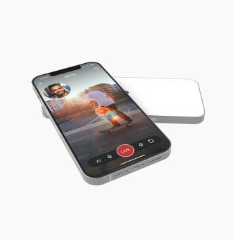


Smart Player Based on ARM Board
Client
European tech company with a serial production facility.
Challenge
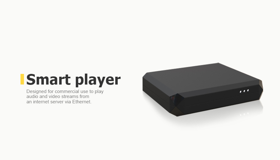
To develop a smart player to play audio and video streams from the internet server via Ethernet. The server should be based on an ARM board with Ubuntu 18.04 server version. The device was planned as a small board and chassis for an audio player with support for OS and drivers.
The Promwad engineering team had to prepare everything necessary to start production at the customer's site. The target market for the new player: commercial spaces, retail stores and food chains.
Solution
-
Concept development
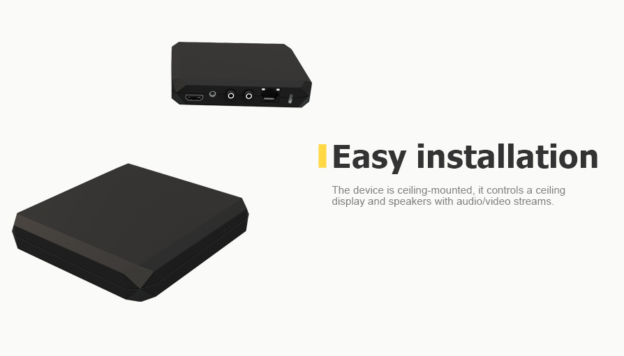
Our first use case was the Starbucks cafe. The device had to be mounted on the ceiling and control the ceiling display and speakers with audio/video streams.
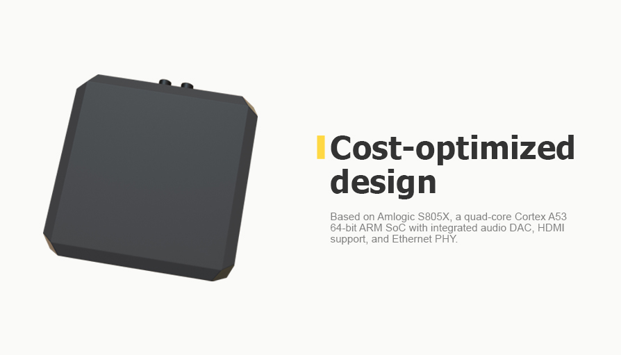
The device targeted large volumes of production; that's why cost optimization and ease of manufacturing were the important factors throughout the development.
-
Hardware design
The designed hardware platform met the following requirements:
- Audio stereo output
- Video output HDMI 60Hz FullHD
- 10M/100Mbit Ethernet
- Low cost
To achieve a cost-optimized design, we decided to use the Amlogic S805X quad-core Cortex A53 64-bit ARM SoC with integrated audio DAC, HDMI support, and Ethernet PHY.
We communicated with Amlogic and received all of the necessary documentation.

Figure 1. Amlogic S805X SoC
The rest of the components were carefully selected in cooperation with our business partner SIE Connect. Using Chinese components and well-known suppliers’ brands allowed us to achieve exceptionally low production costs in our bill of materials (BOM).
These are just a few examples:
- DC-DC converter IC = 0.08$
- RJ45 connector with magnetics = 1$
- USB-A type receptacle = 0.035$
Another requirement was to implement several assembly options for different amounts of RAM and storage. We selected several pin-to-pin compatible SDRAM ICs from Samsung and eMMC memory ICs from Longsys.
To meet cometrial environmental requirements, we did 3D thermal modeling using CAD tools. It allowed us to select an appropriate heatsink for the main SoC, working in the tight integration between the electronics and mechanical team. The mechanical design was adjusted to allow maximum passive airflow without a fan. It allowed us to achieve satisfying thermal performance using an of-the-shelf heatsink and passive airflow.
To verify the thermal performance of the heatsink, we developed a worst-case loading script together with the software design team. We went to a testing laboratory to verify temperatures in a climatic chamber.

Figure 2. Setting up the climatic testing
We passed the testing at the maximum environmental temperature and verified the performance of the audio and video playback across all required temperatures range, and got a test report from the lab.
-
Software development
Our software engineers did the bring-up of the board, checked all components, and patched the Linux kernel to support the new DS1307 i2c bus.

Figure 3. The hardware platform of the device
We developed a flash utility for the testing stand to check GXL and other Amlogic images with the following feature:

Figure 4. Reboot hack for Amlogic CPU reboot
- Fully automated flashing process till the end.
- Parallel flashing of up to 10 devices at the same time.
- Possibility to switch each device and replace it with a new one interrupting the flash processing for another one.
- Components device testing: CPU, memory, MMC, Ethernet, HDMI, kernel, audio, video, serial.
- Manual tests such as LED’s and audio.
- Logs capturing and indication for broken devices that don’t pass some tests.
- Burning AmLogic mode enter.
- Reboot hack for Amlogic CPU reboot.
- The image is erasing on the device.
-
Enclosure and mechanical design
The device contains one printed circuit board (PCB) and has the following external ports:
- power input on a USB-C connector;
- power/reset pushbutton switch;
- 1 RJ45 network port;
- 2 USB Type-A ports;
- 1 HDMI port;
- audio on stereo RCA connector (2 sockets);
- the same audio channel in parallel on a 3.5 audio jack connector;
- SD card slot (at the side of the unit);
- 3 Green/ Red LEDs (at the front of the unit).
During the enclosure design for the device, we studied the client's current products, analogs, and market trends. We have proposed three design options. The first one was a stylized soundtrack with a vinyl record in the middle.

Figure 5. The first version of the enclosure design
The second enclosure repeated the shapes of a crystal or diamond:

Figure 6. The second version of the enclosure design
The third concept looked light and elegant due to its glossy and smooth surface shape:

Figure 7. The third version of the enclosure design
The customer chose the second version of the enclosure design.
Then we started working on the mechanical design. We decided to implement the device in the form of two parts, fastened with four screws. Our mechanical engineers placed supporting rubber plugs at the bottom of the enclosure. Such plugs provide a gap between the support surface and the enclosure, which is necessary for the passive cooling of the electronics.
At the next stage, we chose the enclosure material. There was a choice between metal and plastic. After the thermal simulation, it was clear that there was no need to redirect heat to the enclosure, so we don't need metal. We could use a cheaper and more practical option, such as plastic with a standard radiator.
Then we decided on the following questions. Where is it better to place the holes? How many holes are required to provide the passive cooling of the electronics in the enclosure?
We made comparative passive cooling calculations for four perforation options:

Figure 8. Flow simulation for the enclosure with perforations on the lid and on the bottom

Figure 9. Flow simulation for the enclosure with perforation on the bottom only

Figure 10. Flow simulation for the enclosure with perforation on the bottom (another type of perforation)

Figure 11. Flow simulation for the enclosure without perforation
We saw average CPU temperatures rise from 119.62 degrees to 129.3 with different types of perforations. Calculation models helped us choose the optimal enclosure. It was the second one, with a large perforation at the bottom.

Figure 12. Selected option with perforation in the bottom
Business Value
Our client has a new B2B product: a multimedia player that plays streaming video and audio from a server, retrieving data over Ethernet. It is a very budget-friendly device with passive cooling. Its reliability has been verified by thermal simulations and laboratory tests.
Our engineering team optimized costs and made it as easy to manufacture the product while maintaining its high performance.